How to Assemble a Quick Kit, 2024 Edition
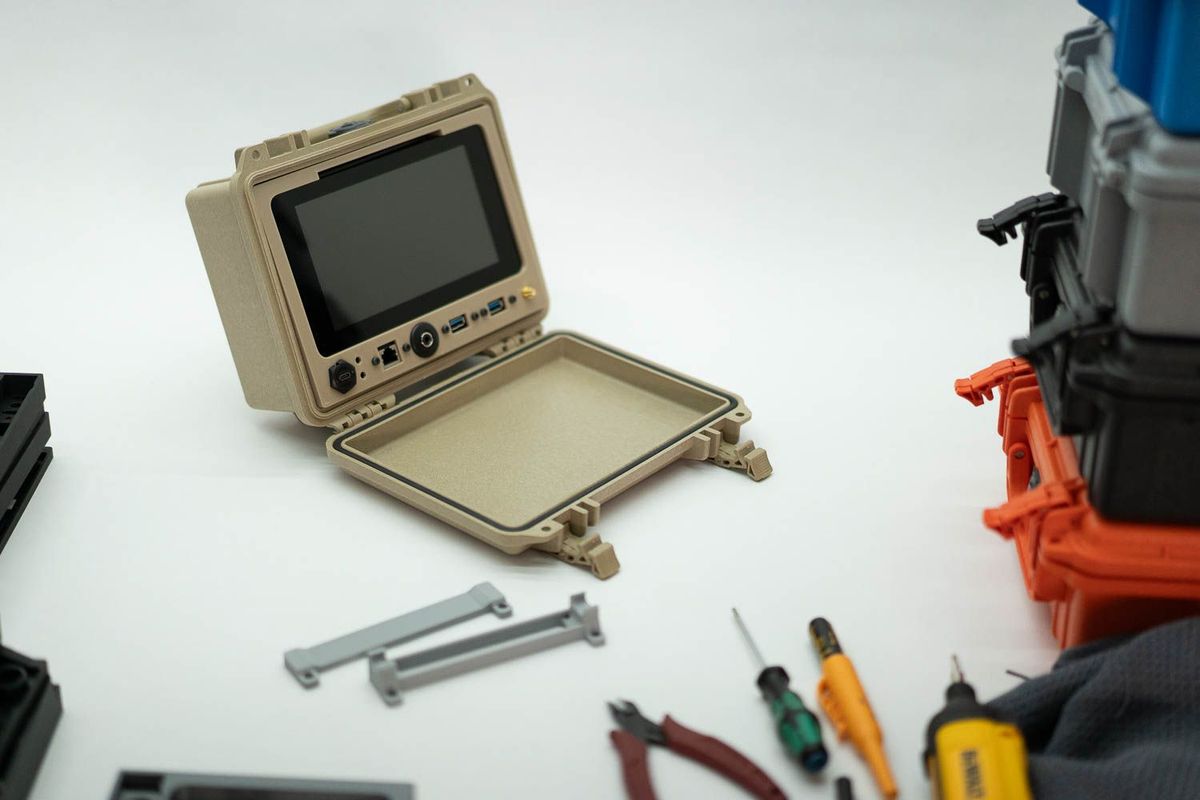
This is a visual guide to assembling one of my Quick Kits. The part design may vary, but hopefully this is helpful to anyone wanting to get started.
Tools you need
Here are the tools you will need. I use affiliate links, which support my work and don't add any cost to you- thank you for your support!
- For the Phillips and Hex Driver, the iFixit "Mako" kit is what I use, and has a ton of bits: https://amzn.to/45kpPiQ
- Small Phillips Head Screwdriver: (Nice, about $12: https://amzn.to/48DwlUT ) or (Cheap, about $5: https://amzn.to/3LM0TK8)
- Hex Driver: https://amzn.to/3F2JOYM
- Pair of Pliers (just in case): (Nice, about $9: https://amzn.to/3ZKAtOH) or (Cheap, about $6: https://amzn.to/3ZHdpAC)
Check your parts! You should have the following:
- Pelican 1150 Case - https://amzn.to/3PI0v0s
- Raspberry Pi Official 7" Touchscreen - https://amzn.to/3F0Qc2J
- Raspberry Pi 4 (8GB model recommended) - https://amzn.to/46k9c8A
- Doscher.com Frame - https://shop.doscher.com/shop/kits
- Panel Mount Ethernet https://amzn.to/46uPlmE
- Panel Mount USB 3.0 - https://amzn.to/3RJ3KHU
- Panel Mount SMA Connector - https://amzn.to/3PY133N
- Panel Mount USB C Power Connector - https://amzn.to/3PYEUT0
- Panel Mount Headphone Jack - https://amzn.to/3LP8tUr
- Right Angle Headphone Jack Adapter - https://amzn.to/3Q0U4XK
- Right Angle USB C Connector - https://amzn.to/3LKqeEC
- USB Extension Cable - https://amzn.to/48BWIKQ
- RTL-SDR Dongle - https://amzn.to/3PHSjgG
- M3 x 8mm screws (10 total) - https://amzn.to/3Wz0oYE
Assembly
Once you've made sure you have everything you need, let's get started with preparing the display. Take it out of the box and open the little bag of accessories.
Place the display face down on a soft towel, away from any sharp or rough objects. You'll find four small Phillips head screws, a small flat white cable, and a bunch of small wires, usually in different colors like black, red, yellow, and green. For this project, we'll only be using the red and black wires. You can save the rest in a bag or a spare parts bin; they might come in handy for another project later on!
Next, let's unbox the Raspberry Pi 4 computer. Even though the Pi5 looks pretty similar, we're using the Pi4 for this guide. You only need the board itself.
Take out the two panel mount USB cables from their bag and keep the screws that came with them aside. We'll be using some cool hex screws that are a bit longer, and they work perfectly with the Quick Kit.
Attach USB Ports
Connect USB to Panels - In the package you received, there are two USB panel adapters or cables. The holes on these adapters align perfectly with the Quick Kit frame. While it's optional, it's a good idea to make sure the same orientation (top/bottom for the connector) is maintained during assembly. Here's how to do it:
Use the hex screwdriver, either the Wera one mentioned earlier or the bit labeled "2.5" from the hex kit in the iFixit bits. Then, simply screw the USB port onto the Quick Kit frame as demonstrated in the image below.
** Beware, if the screw is binding, then you are cross-threaded, and re-insert properly. If the screw goes in a little, but then spins, use the pliers to squeeze the plastic part so the nut inside the plastic USB part can't spin. This happens about 10% of the time. **
Attach the Ethernet, Jack
With the hex screwdriver (either the Wera one mentioned earlier or the bit labeled "2.5" from the hex kit in the iFixit set), attach the Ethernet port to the Quick Kit frame, following the illustration below. Be sure to position the small clip on the Ethernet cable so that it's facing upward; otherwise, you'll encounter difficulties when trying to insert or remove the cable later.
Attach the Headphone Jack
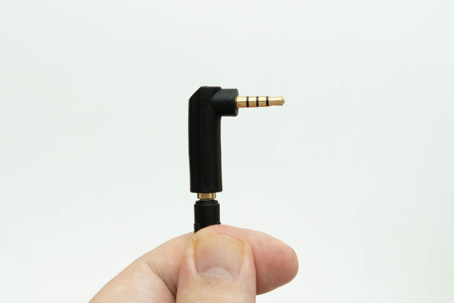
This is pretty easy- unscrew the collar on the panel mount for the headphone jack, then place the headphone hack on the panel frame, then thread on the collar. I don't recommend using any tools to tighten this collar- hand tight should be find.
The headphone cable will need the right angle adapter on it like so:
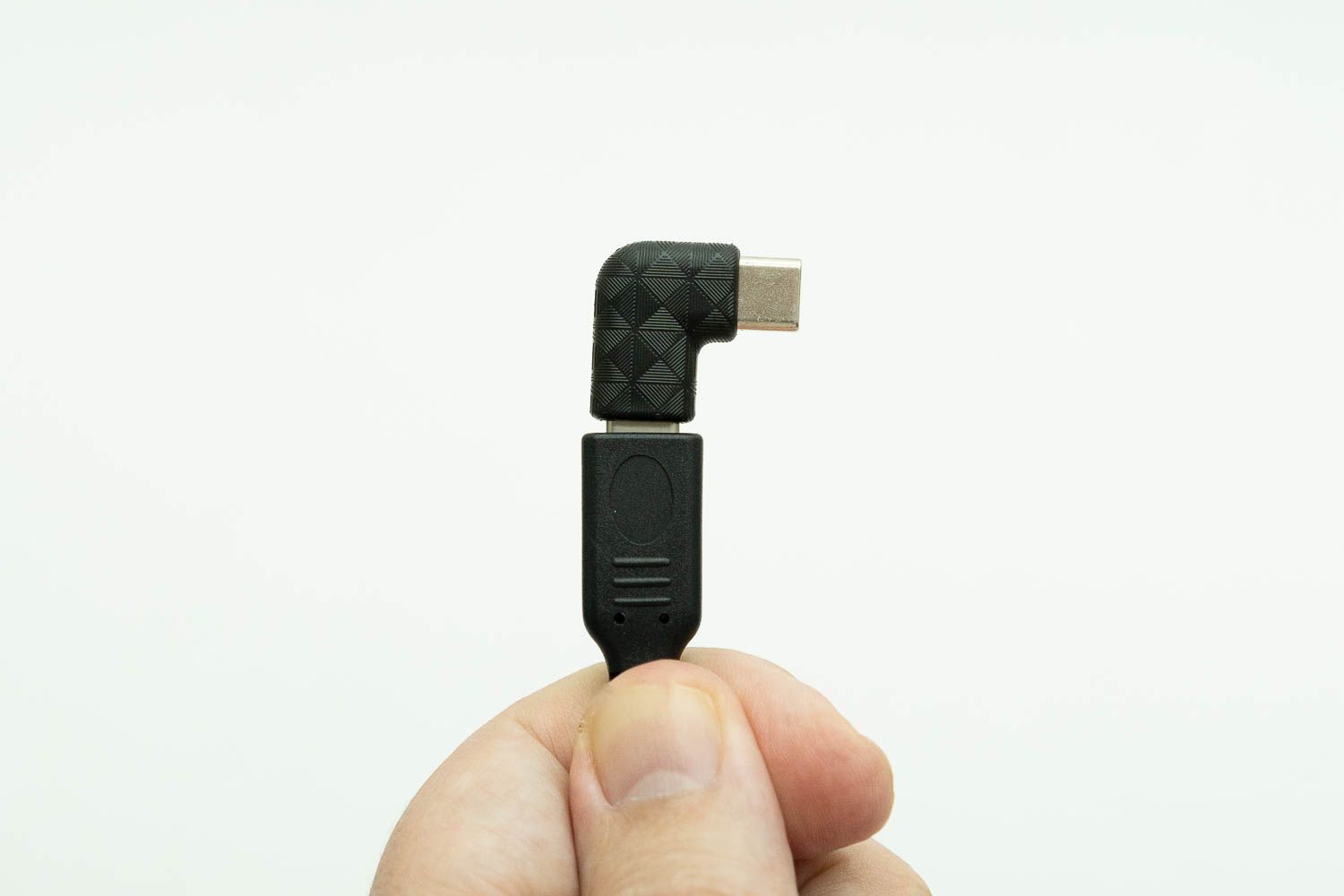
Attach the USB C Power Connector
Attach the USB C power connector just like the headphone jack, but observe the USB C power is "keyed" so it goes in at a fixed angle and won't spin. Hand tighten this one too- if you use a tool on the front you will scratch or mar the front of the Quick Kit. The USB C power also needs a right angle adapter on it, just like this- it's easier to add after you've mounted the port to the plastic frame.
Install the SMA/Radio Connector
Attach the SMA connector for the radio cable, being careful not to scratch up the front of the frame. When it's all done, it should look something like this:
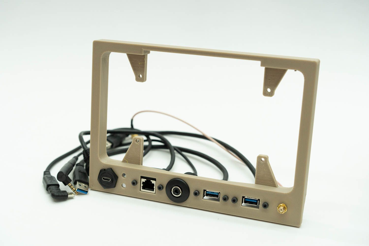
Image & Install the MicroSD card
Image SD Card following this guide:
Insert SD Card into the Pi4 - it is really hard to get it into the card slot after you install the ribbon cable for the display.
Attach the Ribbon Cable to the 7" Display
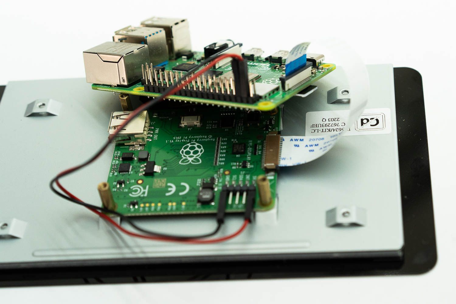
The DSI ribbon connects to the Pi and provides the touch controls back to the Pi as well as the display signal. The cable is very picky and the connectors are sensitive, but if you do it right and leave it alone, it works great. Note this picture helps with pins and how to orient the cable (look at the print on the cable and the blue mark on one end- that is how I do it!), but look closely- you can see the cable has come undone a bit. If this happens, release the cable and re-attach. The physical installation instructions here are also over at raspberrypi.com.
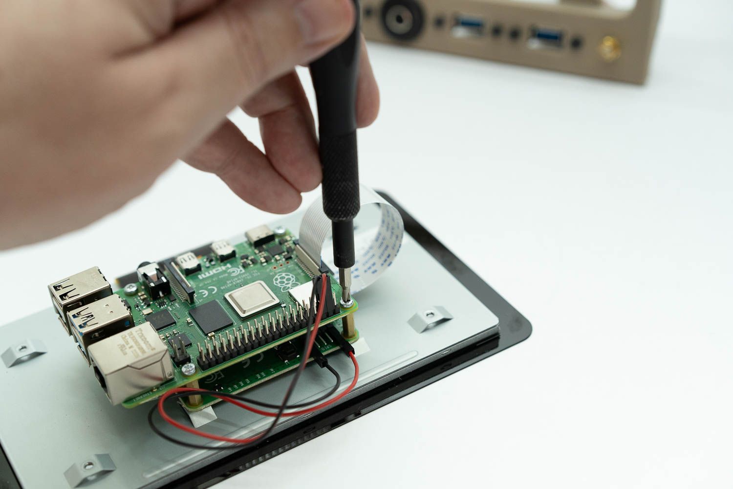
Attach the Pi4 to the Display
Attach Display and Pi4 Assembly to the frame
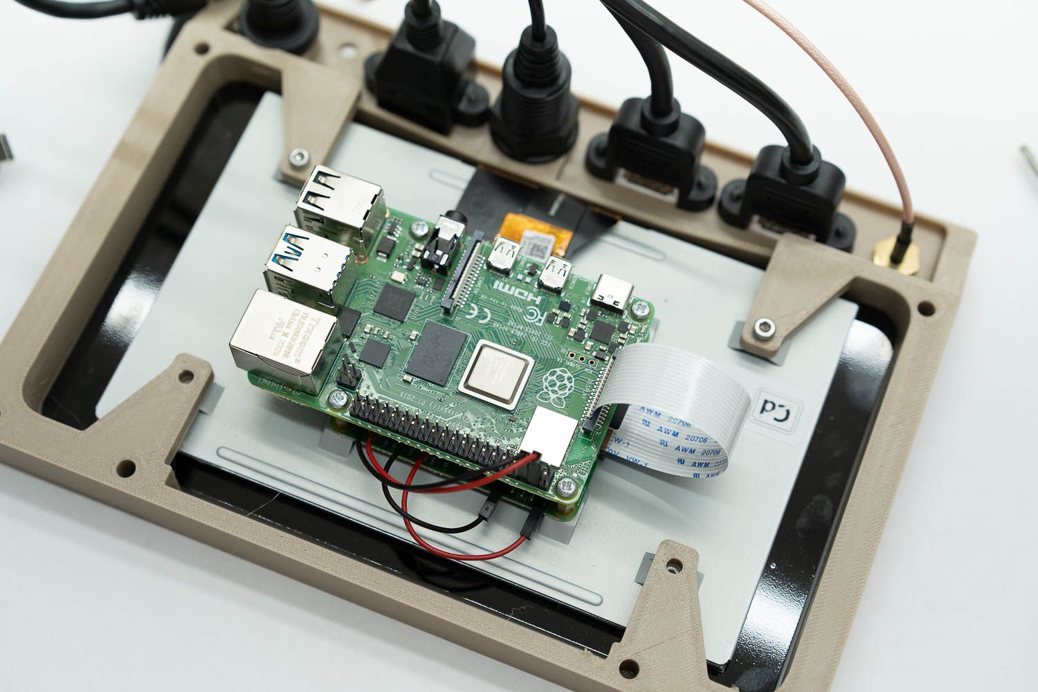
Place the Display and Pi together inside the frame, oriented as shown below:
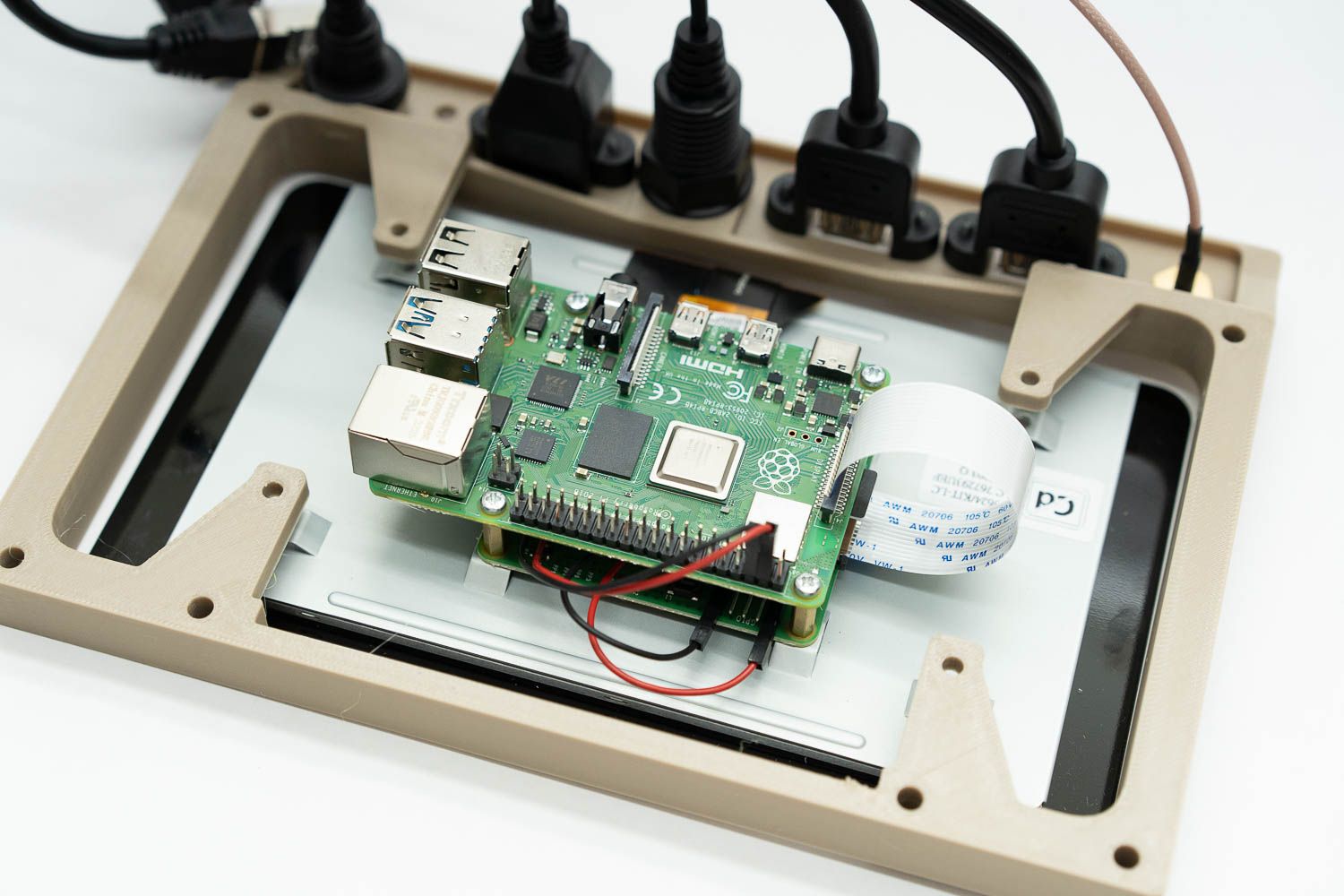
Once there, carefully lift the display to meet the holes. If you are adding the optional SDR connector, you should only add the bottom two screws, since the SDR connector piggybacks on the other two. With just two screws, it looks like the photo below- but note I also gently tucked the red and black 5v power wires underneath the Pi4 to keep them out of the way.
Final connections
Attach the SDR bracket to the top 2 holes of the display frame- the screws should be just long enough to attach both the SDR bracket and the frame to the Display.
Connect all your connections, being patient and gentle- remember those right angle ones may require a little creativity to get in there.
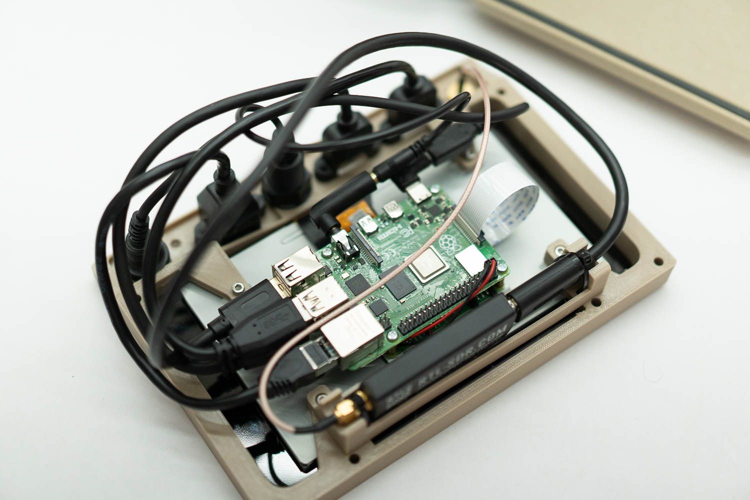
That's it! Gently insert the assembly into the Pelican 1150 enclosure. The wires may push gently against the sides, but this slight tension is what helps hold it in place! Thanks for reading along, and enjoy your cyberdeck! You can also check out other wildly different designs for cyberdecks over at our friends in the Cyberdeck Cafe.
Comments ()