the Raspberry Pi Field Unit
Looking back on old projects is a great way to see your original vision and how tools and materials have changed.
Back in 2015 I was working on one of my long-term hobby projects- a cheap, durable, and easy to make solar tracker. An offshoot of that project was my old “Raspberry Pi Field Unit”, which was a Raspberry Pi Model B in a weather-resistant enclosure. It had a specific purpose- to run off any power source, including 12V or higher, and run motor controllers for a solar tracker. There were several deficiencies in my design, and Hackaday commenters were quick to point that out. To be fair, Hackaday readership is a tough crowd.
Making this project was expensive and messy. I outsourced most of my metal and plastic fabrication. Specifically, I used local providers for waterjet cutting and doing brake bends on parts, while I used Big Blue Saw for cutting parts out of sheet plastic. As you can imagine, learning about scale drawings was expensive- at least once I made a simple mistake of doing millimeter scale instead of centimeter, meaning I got back parts that were a tenth the size they needed to be and useless. Apply this same concept to iterating through design choices, having part fitment issues, and pretty much every problem CAD tries to solve today.
There’s a distinction to be made between low volume production and rapid prototyping. 3D printers are especially well suited for rapid prototyping, with parts printing in hours or sometimes days. The challenge is still one of strength and heat for many 3D printers though- home printers print most plastics at up to about 250 degrees Celsius (or about 480 degrees Fahrenheit), which is fine until you start working with parts on cars or parts sitting in the sun. Parts can get soft and/or weak in lower temps, and UV breaks down some plastics, although there’s a real gap in formal testing of different plastics in different climates.
Where fabrication using waterjet cutting of plastic and metal starts to make sense is for these same areas where plastic/FDM printers start to show a little weakness. A big factor in this project was that I didn’t know the benefits of waterjet cutting and 3D printing, and frankly I fumbled through some of the fabrication. It’s important that when considering a project, you think about the tools and materials you’re going to use and have those inform your design decisions. Use materials and processes that align with the project.
My learning curve didn’t end there- many parts I needed were not available off the shelf, so it meant custom soldering boards or parts, as well as using wiring and interconnects between parts that weren’t designed to work together. I also had very little understanding of appropriate wiring sizes, leading me to use gauges of wire far too heavy for what I needed, adding bulk. I also didn’t have much of a concept of wire looms or management.
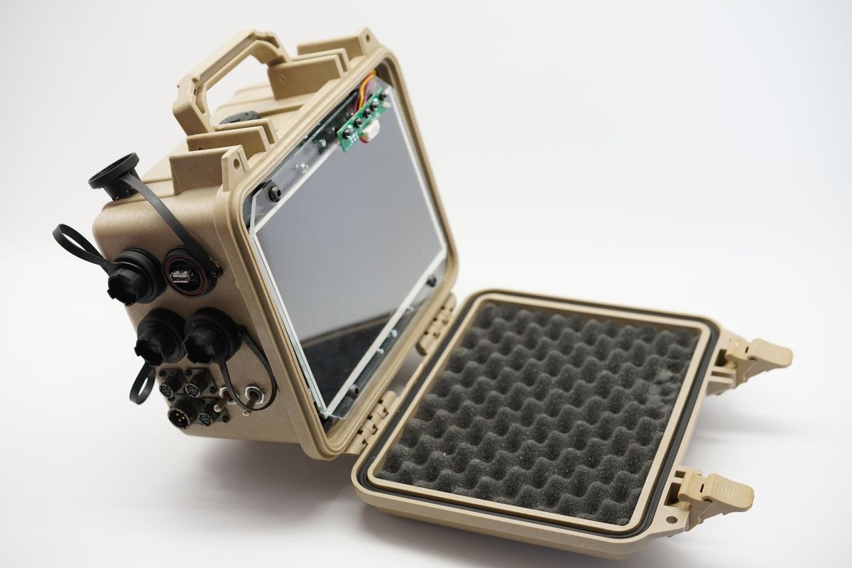
In the photos above you can see how crazy complex the system was, which incorporated:
- An Adafruit 10” HDMI LCD screen that ran off 12V with its own breakout board
- A Raspberry Pi Model B (today’s version would be something like the Pi 3B+, since this case doesn’t allow for active cooling)
- A dual channel, high current 12V motor controller (discontinued)
- Step-down DC to DC converter, allowing high voltage power input and powering the 12V display
- 12V to 5V to power the Pi. This one is cheaper than the solution I used.
- Adafruit GPS Breakout on Amazon or Adafruit
- Adafruit RTC breakout on Amazon or Adafruit
As you can see the wiring is a mess, and I debated on whether I should show the wires or not- I’m not proud of them, but as a first major project I’m not ashamed of them either- we all start somewhere.
While this was purpose built for my own project, it has a certain post-apocalyptic or cyberpunk feel too it- but as I’m sure you noticed along with Reddit, it’s missing a keyboard and not at all EM proof, according to the internet here.
The entire project does squeeze into the case however, and some mildly dewy mornings didn’t give me any problems- despite me turning a weather resistant case into swiss cheese- see the photos below. One is an older case that I practiced on, and if you look close you can see some of the holes are very rough, I tried different drill bits with some laughably bad. Spade drill bits were terrible, since they’d grab into the plastic and torque hard and take big bites out of the plastic. Forstner bits also did the same thing, or they’d overwhelm my drill press and get stuck. I needed really large holes and larger than traditional bits would do, and eventually stumbled on step drill bits, which are amazing for multiple projects. If you look at the clean holes in the photo below, those are from the step drill bit.
Fast forward back to today, and you can see most of the connectors are doing well, but those USB connectors did not age well. They’re actually really fragile, and there are more durable ones from McMaster Carr or Amazon- not all are liquid resistant though.
I probably get the most questions about the mil-spec connectors though, which I still love and use- even though a connector pair is easily $30 or more. Let that sink in- a single connector is roughly the price of the SBC. That assumes you want to hand-solder all of those wires too, since the crimper is $500.
As we round out the restrospective, there’s one thing that really bugged me about this screen- it had terrible, and I mean terrible mounting options. The tabs were tiny and really only held the screen a bit, since this screen was expected to be surrounded by plastic. At this point I was still measuring with a ruler, and not the digital calipers I use today, so getting parts cut that would reliably match the tabs was too daunting for me.
I’m still proud of what I did though- I sandwiched the display between two laser-cut pieces from Big Blue Saw, and then held those together with M4 screws. This protects the display and keeps it from moving too much and straining the tabs. I was also ill-equipped to take on rounded corners as well, something I am just now getting comfortable with.
With a wider shot of the screen, the aesthetic fits though- I still like the look of it today, but I’m going with John Park’s advice and leaving this as-is. I could easily upgrade the Pi but it’s better to leave it alone.
Comments ()