The Recovery Kit 3
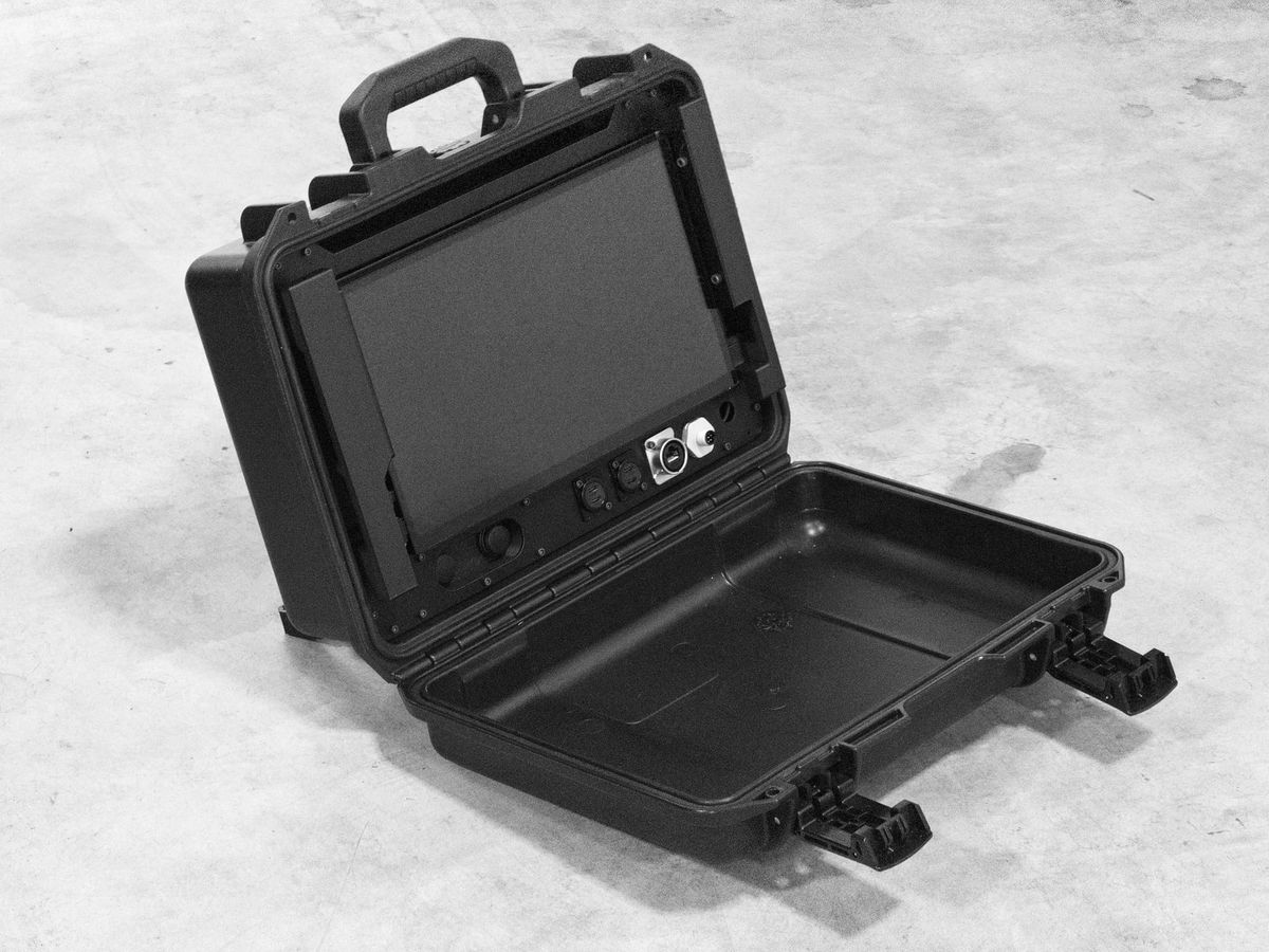
Quick Note: I started writing this a few months ago as I finished up the last few bits on the Recovery Kit 3, and some changes delayed things a bit. First, my startup license for Fusion 360 is nearing its end, but miraculously Solid Craft started up and it's been wonderful so far- and the design has actually been finished up on the app. I recognize that Fusion may be included for some of you as your daily profession, but for many hobbyists its format has been a barrier to editing my files. Starting with this project, I will be releasing the full files as edited in SolidCraft to paid subscribers. Once I figure out how to do it reasonably, I will release the files for older projects too. Thank you for reading, and I hope you enjoy!
There's some nostalgia here as I write this, looking back at the original Raspberry Pi Recovery Kit, the Recovery Kit 2 and 2b, and the many other small projects along the way. The Recovery Kit series has seen every iteration I can think of, especially with finally adding substantial battery support in this project.
One of the things that I spent time thinking about is looks versus function for this build. The outside looks matter to me as always, but the wiring left me considering function or form. I chose function over form, keeping the wiring as simple as possible over making it visually interesting. You'll note the zip ties- that is intentional here.
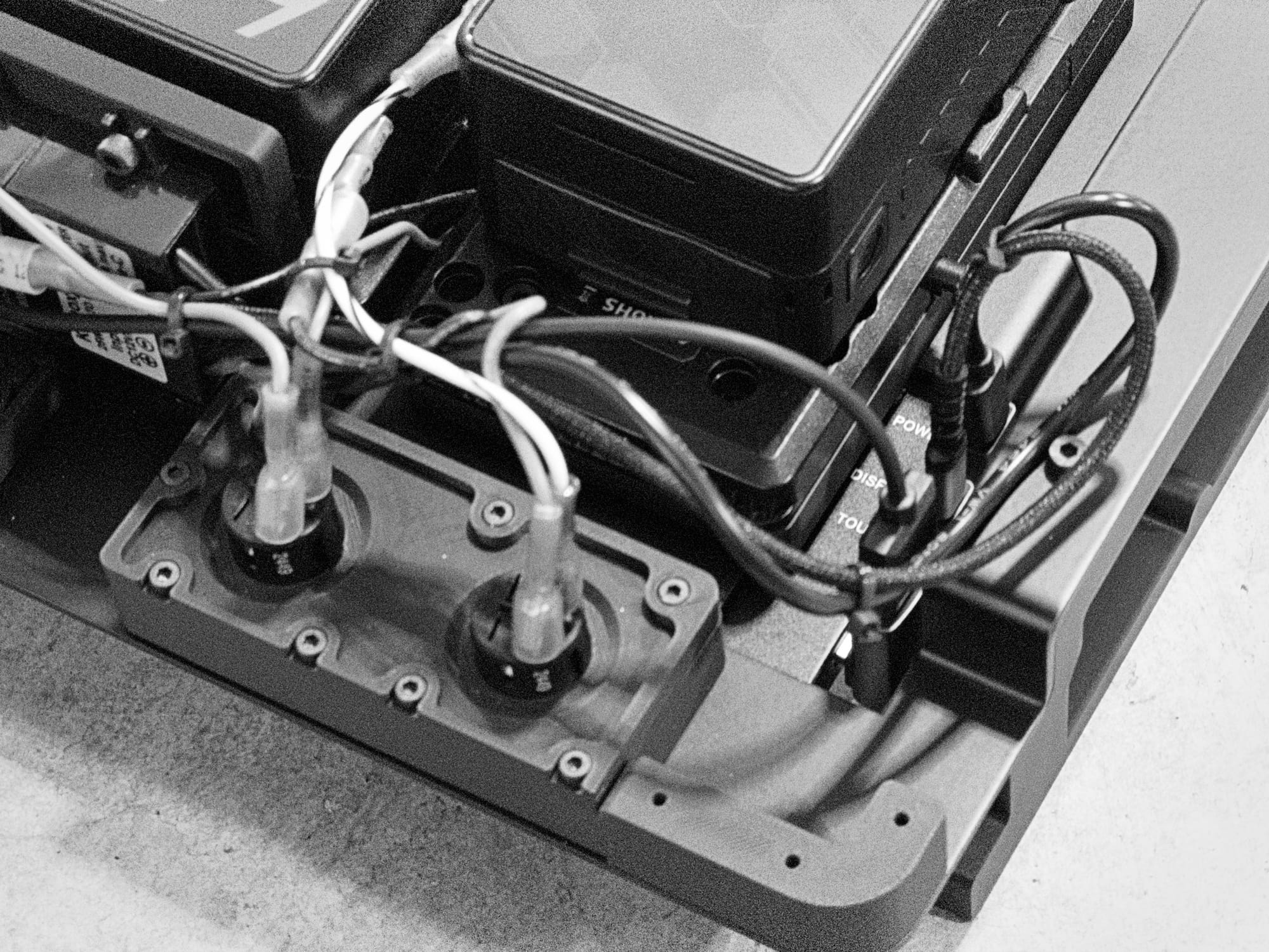
I've always tried to make each Recovery Kit ready to up-cycle and harvest for the next version, and this is no different. I'll get into that more below, but overall I have made a cyberdeck with a beautiful screen, dual batteries, fully modular for different CPUs, and no soldering this time to make it as easy to build as possible while still keeping the Recovery Kit aesthetic.
I fully recognize that cyberdecks have had a bit of a moment on social media, and that's pretty fun to watch- but I found may own way into this community a few years back and it's been interesting and fun to see some new questions as well as the same repeated questions around design, function, fabrication, and more. Some blogs and news aggregators have stuck with the community better than others- and the site that best covers this community for 'decks has got to be the Cyberdeck Cafe.
Frame Breakdown
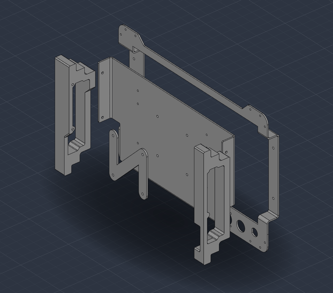
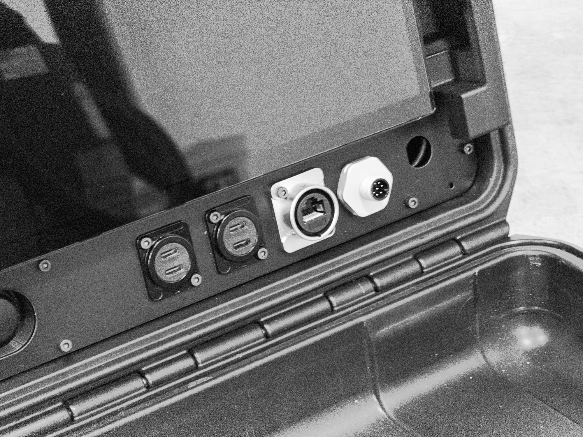
In the front there are four components you will readily see while looking at it- the main frame, which is the largest part made of bent aluminum from Send Cut Send (not sponsored) and required since the stress of wedging into a Pelican case and the size of the enclosure means 3D printed did not work for me. I'll be showing CAD for most of these breakdowns simply because it's easier to see than the matte black plastic and powder coated metal parts. The main frame has the holes for the panel mount connectors like USB and Ethernet, as well as the GPIO pin port. It also has a notch on each side where the 3D printed handles go- I chose matte black PLA, but they print flat without supports so you could make whatever you wanted to out of them.
The handles connect the main frame to the panel mount, which has a depth designed to give airflow around top, bottom, and sides of the display without giving up front area that vents would normally need- this is probably one of my favorite design features. The display bracket is sized for the display included in the parts link, which happens to be a 2k 13" AMOLED display- but since it uses VESA holes on the back you could probably mount something different in a pinch. You could also just modify the design for the display bracket without redoing the whole project too. It's the second and only other metal part, also powder coated aluminum. I also have a spacer, which helps me use a standard sized M4 screws and provide clearance for screw heads for rear-mounted parts, but you could make it thicker by a bit- but remember the cables connect around the handle on one side, so moving the thickness too much could change the fit there too and make a problem. Here they are exploded out:
Rear
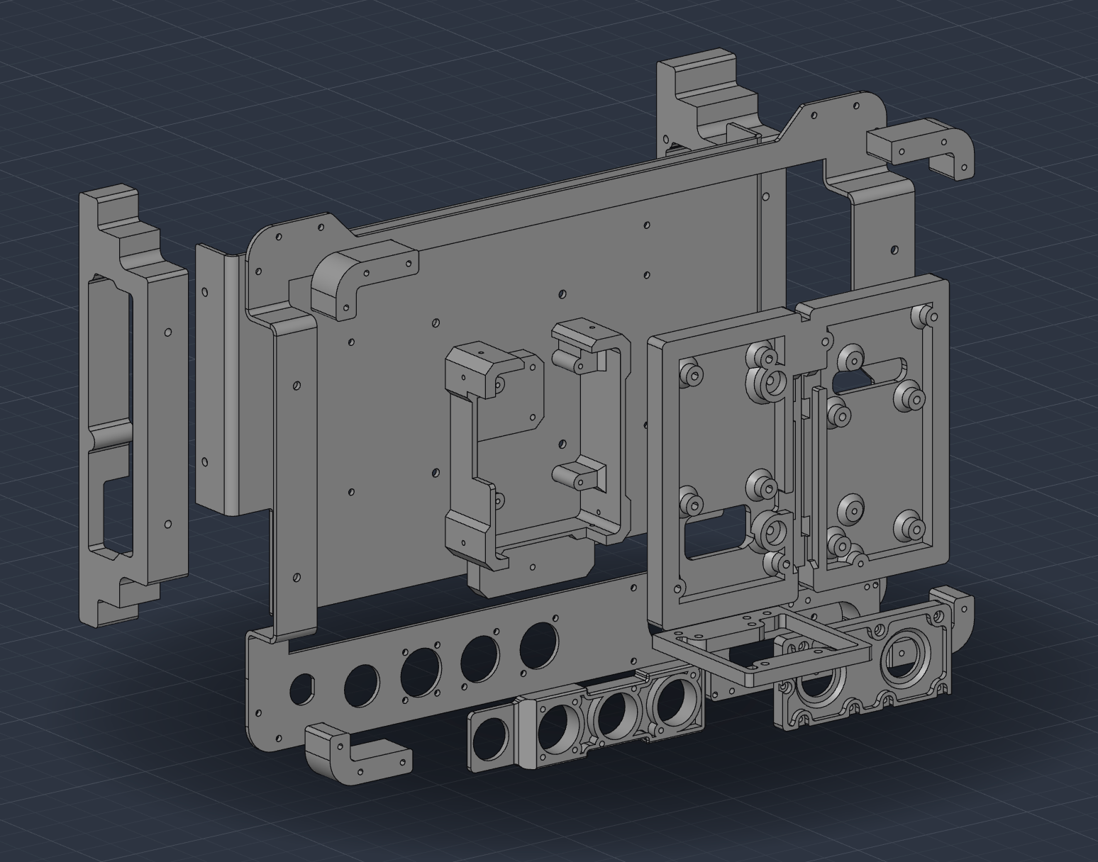
The rear will be a familiar view with some new components- I left the front parts in this view to help provide some context, but the rear parts are pretty obvious:
Compute Unit - lent from the last Compute Unit project, this holds a Raspberry Pi 4 but could easily hold a different SBC- but remember this config needs to run off 5V, so most Intel setups would need a different inverter. You can print the full cage/cover of the compute unit, but I chose to leave it bare for my build. Just to the right the big 3D printed plate is the star of the show- it holds the quick-release battery brackets for two 99Wh batteries. One is rotated 90 degrees from the other so that the quick release buttons are on opposite sides- no complex circuitry here, just one battery for the display and one battery for the Pi. Each is run through a simple pushbutton toggle switch on the front panel, allowing you to hard power off other component from the battery, helpful during swaps or long storage periods. There's a small 90 degree bracket at the bottom, it holds the two 5V DC-DC inverters for the batteries to power the display and the Pi4.
Finally, there are spacers for the panel mount components and the corner parts to help provide a snug fit into the Pelican Storm iM2200 case.
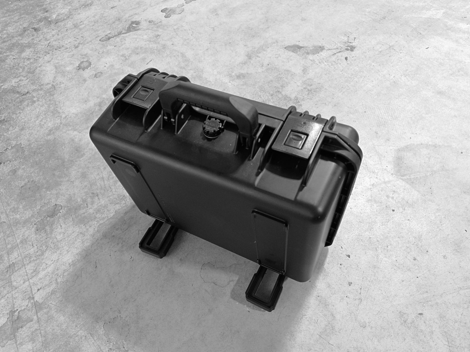
All assembled, it drops snugly into the Pelican case, but you want to print a couple of these feet to wedge into the space below the hinges, this case does not rest neatly for a cyberdeck the way the Pelican 1150 and 1300 do.
Here's another angle from the back and bottom:
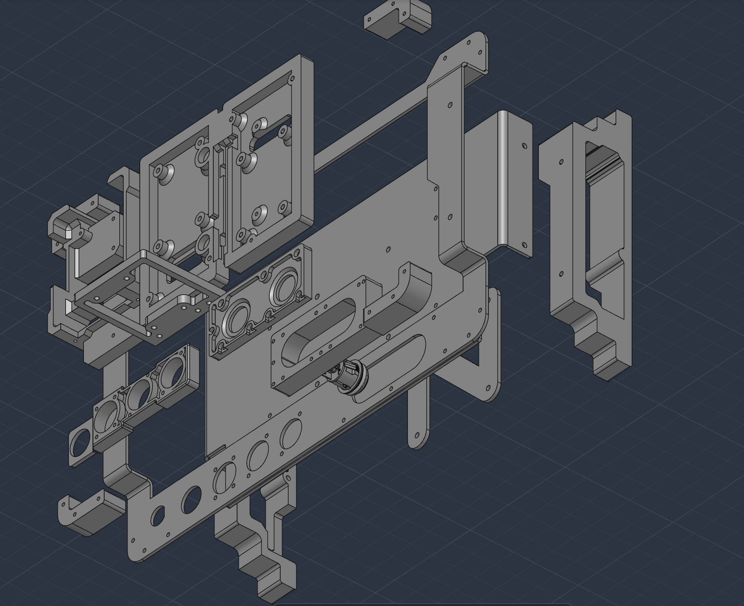
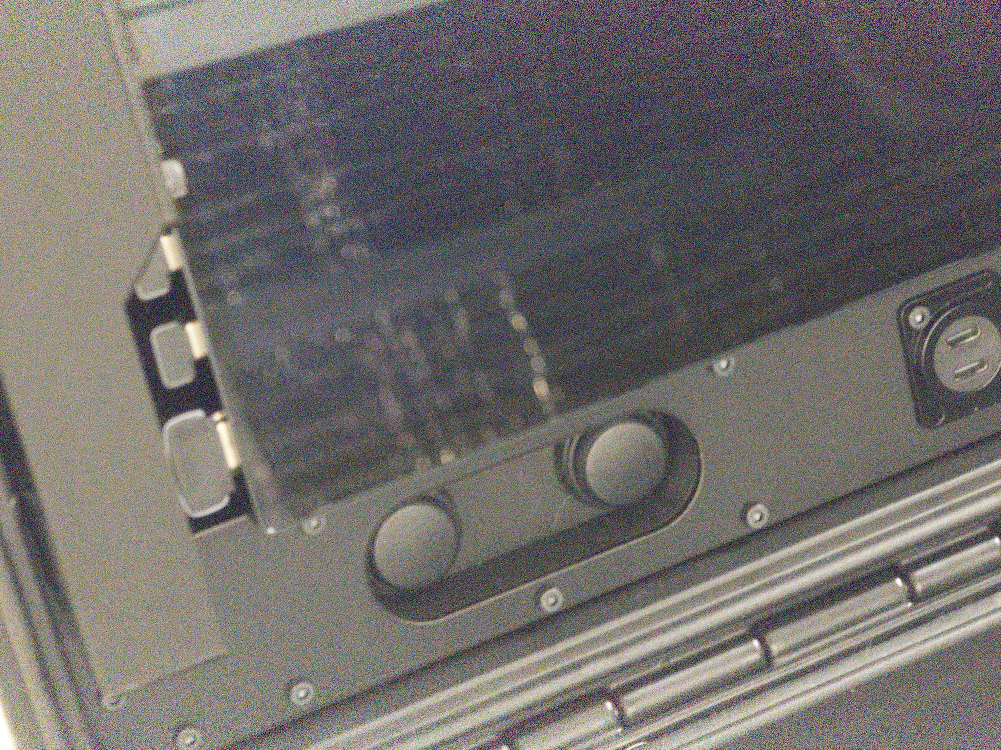
The pushbuttons for power are recessed to keep them from accidentally powering off the system, and the spacer for that has been incorporated into the corner widget too. If there's anything that's really complex here, it's the assembly of the battery plate and the display, they mount on opposite sides of the display frame, so there's an order to it- but it's not too bad. As always, no instructions- part of the fun of these builds is figuring this stuff out and modifying it to your liking.
The Compute - Bring Your Own
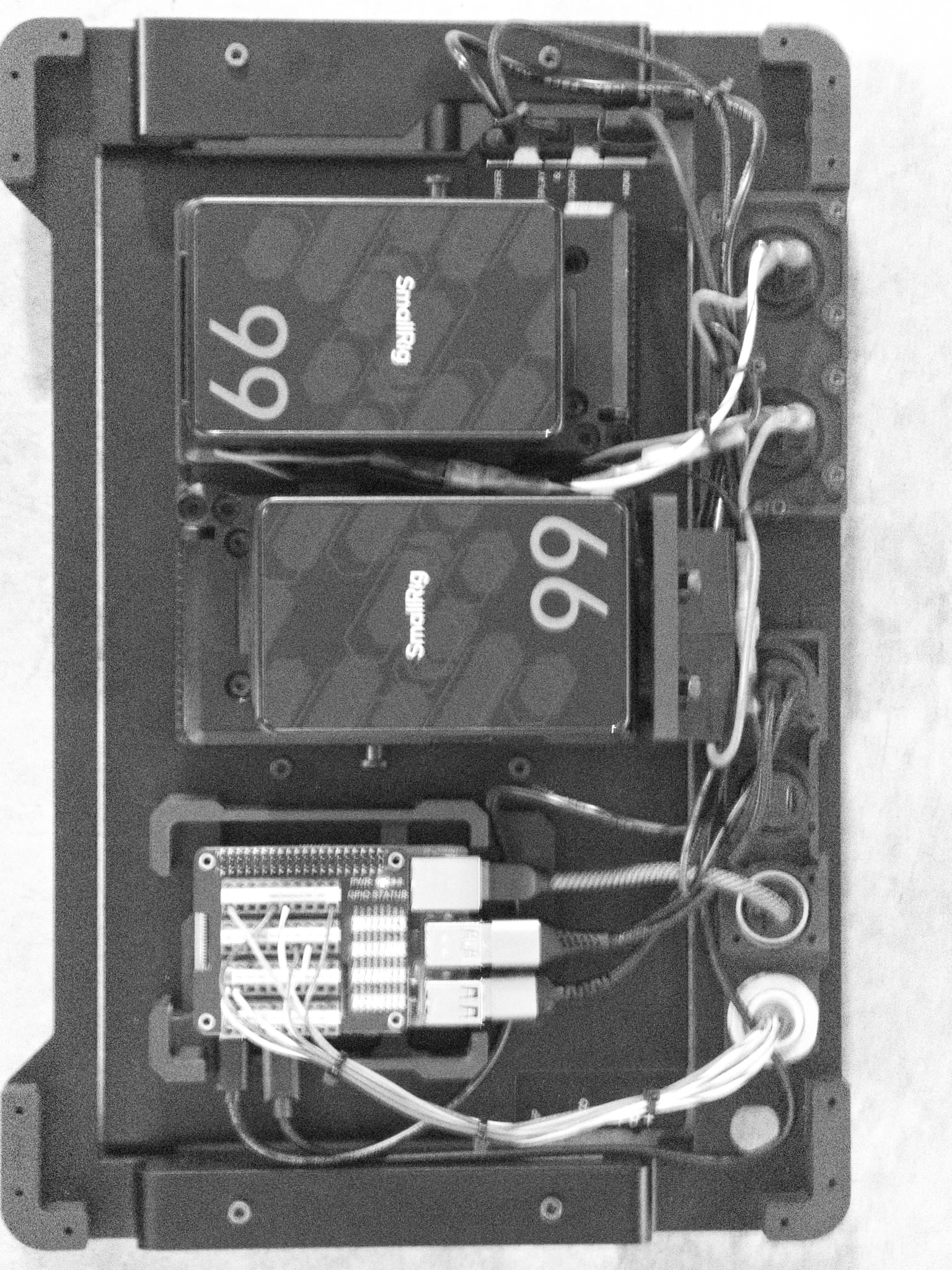
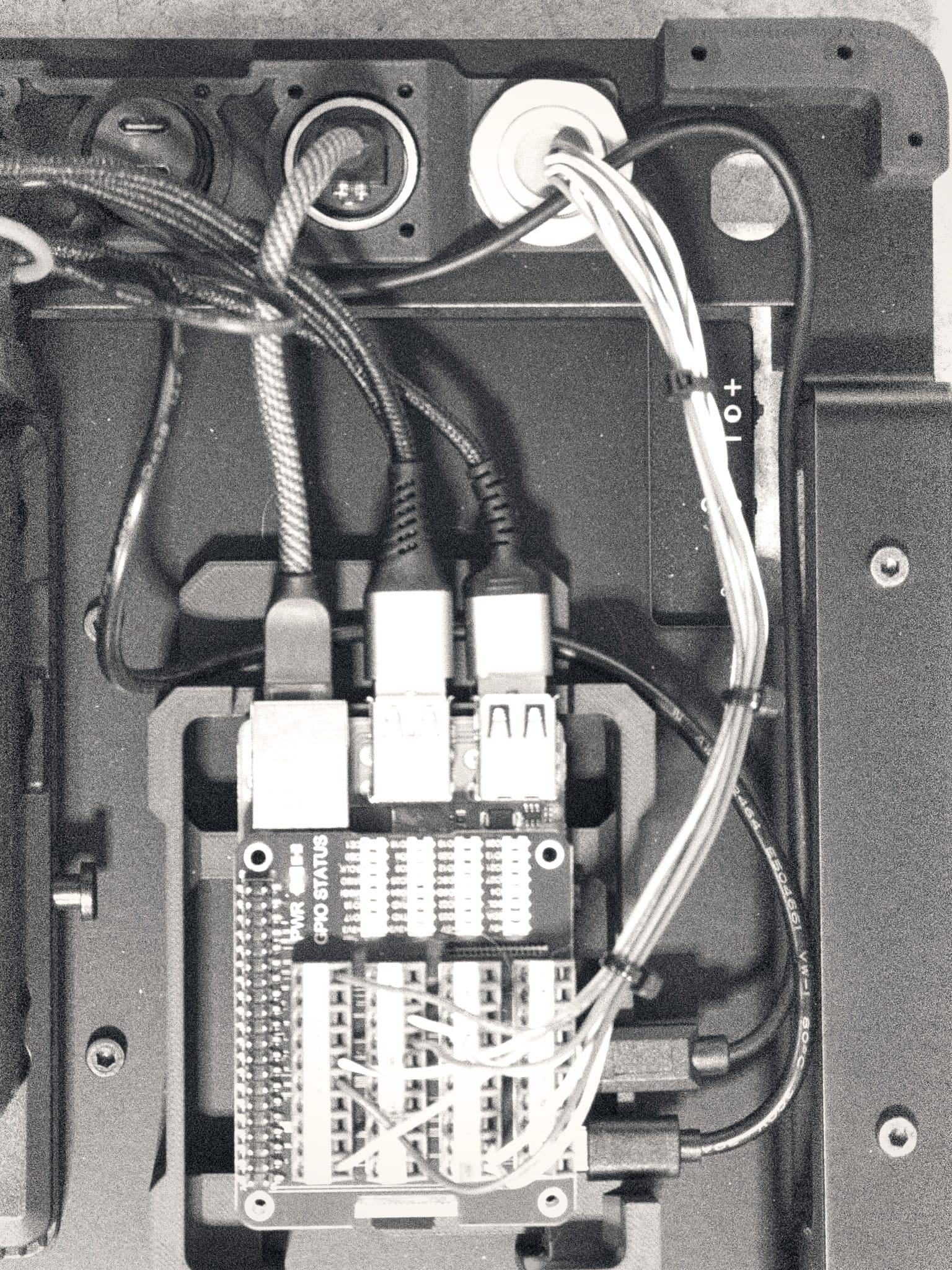
The compute area of the RK3 is shown and assembled here with a Raspberry Pi 4- it could easily be a Pi5 or even something else, but for this build I want to keep it realistic especially considering how expensive a Pi5 is for what it does. I am using the Compute Unit project for the base, but with a custom lower/Pi mount that attaches to the main frame of the RK3 with MX screws spaced at 100mm. There are technically three vertical screw holes, with them spaced 75mm and 25mm. These spacings are meant to be as flexible as possible for other compute units that you may want to design yourself, and as easy to model as possible. The main customization around the Pi4 was clearance for all the cables coming in and out of the Pi, so if you went with a really minimal mount it would be direct to mount whatever you needed.
GPIO
In my Recovery Kit tradition, I have added a panel screw mount for GPIO. The pin header is meant to be easily modified as well, so you can re-map any of the pins on the panel mount to any of the GPIO you may want, allowing you to externally mount sensors, or even additional hardware can be wired through them in the future. This has always been about letting the Recovery Kit be more than just a computer. This way you can wire the panel mount to the specific GPIO pins you want to use, wire up a custom cable to match, and attach to the cable a servo controller, temperature sensor, accelerometer, light sensor, or even an air quality sensor.
Dual Batteries
The dual batteries are easy to pop in and out, and lock in place with a release button. One battery powers the display with an on/off pushbutton switch on the front panel, the other powers the Pi. Each is a 99Wh battery, so the runtime is as good as I can get without going full custom pack. The batteries are not hot-swap though, there's no circuit to buffer the component they power, so removing the battery for the display or computer cuts power to that component.
Display
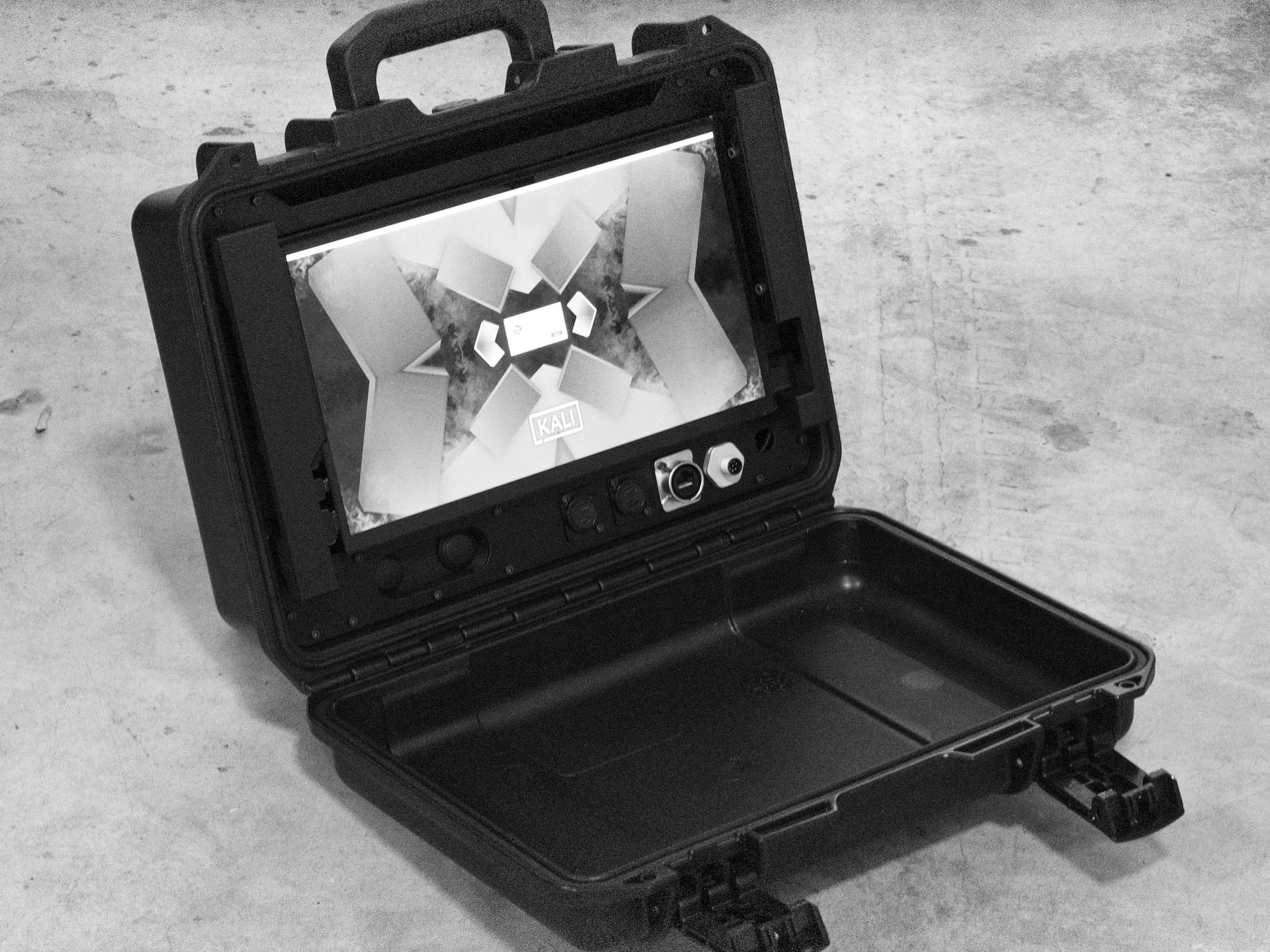
One of the key areas of improvement after the battery is the display- this is a beautiful AMOLED display that's around 13" and works via HDMI, so it doesn't have the baggage of the native Raspberry Pi displays with their DSI connectors, and this one is still multitouch via USB, so you still can use this with Linux or Windows out of the box with no drivers.
Main Chassis
Finally, the main chassis is a mix of powder coated aluminum and 3D printed PLA, although any 3D printed parts would do here. The goal was to create as much rigidity and venting/airflow as possible. Going with a larger Pelican case meant a case bigger than the print area of my printer, so printing the full front panel was out of the question. This leaves the metal frame to cover the full width and height of the panel, but with key plastic handles and other tidbits to keep it light and functional.
I tried my hand at keeping this more industrial looking, something more from a dystopian organization and less like a military artifact, with some extra ports and options for later, so it's not so polished.
Design Files
As per usual, you can get access to my design files by signing up with any tier of paid membership. These projects are increasingly time intensive and costly to build, so your purchases help significantly. Thank you
To support these projects, design files require a paid subscription- these builds are time consuming and parts are more expensive than ever. The Design Files Post is here.
Parts List
- Pelican Storm iM2200 Case (Black): Amazon
- Waveshare/Generic 13.3" AMOLED Display: Amazon or Waveshare
- Two (2) SmallRig 99Wh V-Mount Batteries: Amazon
- Two (2) V-Mount Battery Mounts: Amazon
- Two (2) Pushbuttons for Power: McMaster Carr
- GPIO Shield for Raspberry Pi: Amazon
- Two (2) DC to DC inverters: Amazon
- M4x10mm,12mm,14mm Screws
- M2.5x8mm Screws
- M3x8mm Socket Head Screws
- Right Angle HDMI: Amazon
- Right Angle USB: Amazon
- Two (2) USB Cables (Pi to Panel Mount): Amazon
- Two (2) USB Cables (Display to Pi): Amazon
- HDMI to Raspberry Pi 4 Display Cable (remember to change this if you use something besides a Pi4! Roughly 2ft should be ok): Amazon
- Short Ethernet Cable: Amazon
- Zip Ties - What do you mean you don't have zip ties?
- Panel Mount USB: Amazon
- Pabel Mount for GPIO: McMaster Carr
- Panel Mount Ethernet: McMaster Carr
- Crimp-Style Spade connectors: Amazon
Comments ()