GPS locator
When GPS was first released to consumers, it wasn’t even in the hands or understanding of most people. Early on it was used for pretty unique and esoteric stuff, and in the age before ultra-connected devices that use common smartphone apps, there were GPS receivers.
They pretty much just displayed current coordinates including latitude, longitude, and altitude- not much else. There’s a great set of old devices over at retro-gps.info. The old units are big, heavy, slow, and use a ton of power for what they do. Modern GPS units are light, small, cheap, and use very little power. I thought it would be cool to revisit the idea.
What would a newer one look like, and why not s smartphone? First, too much reliance is put on a smartphone, and without the need for maps a smartphone is overkill (and a solved problem). Second, the device I planned to build wouldn’t need internet, and should be as easy to hack/modify as possible. We don’t need a full fledged OS either- too many moving parts, even though a GPS sensor would be easy to add to the Recovery Kit.
Finally, I wanted something as easy to build as possible- a minimum number of parts and as easy as possible- so no soldering (even though that’s an important skill).
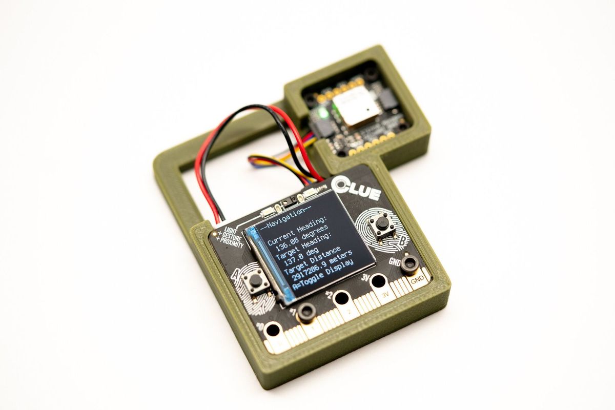
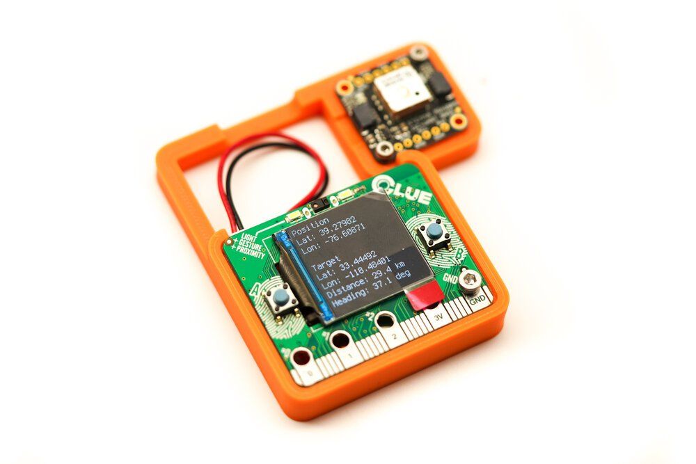
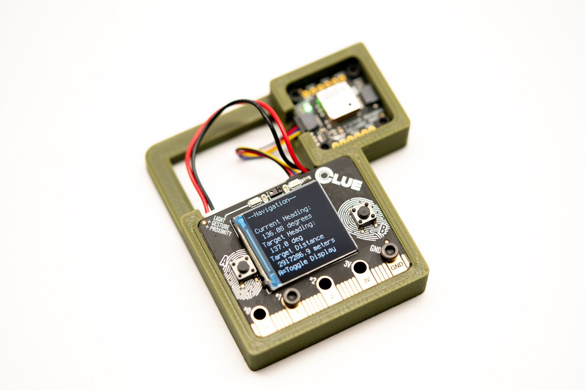
So to sum it up, the device has one primary goal- to show you your location, but with a single added feature- help you find your way to another set of GPS coordinates. The device will show you your current GPS stats, but also the compass heading and distance to your destination (target).
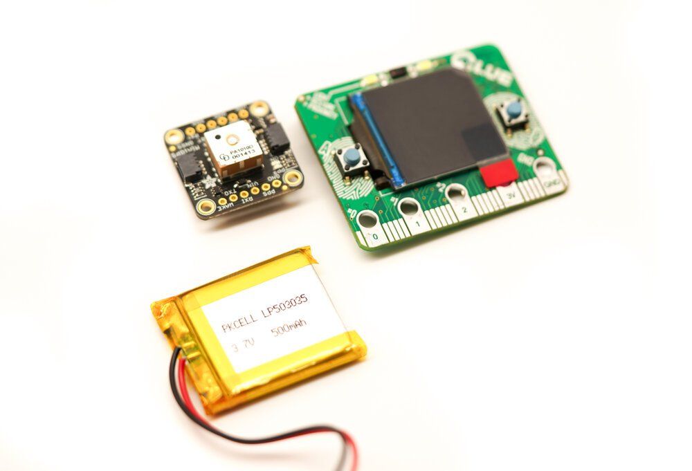
Adafruit CLUE board - (Adafruit)
- Adafruit Stemma GPS Board - (Adafruit)
- Adafruit 50mm Stemma Cable - (Adafruit)
- LiPo Battery - (Adafruit)
3D Filament (your choice, only one is needed)
- Olive Green PETG - Amazon
- Orange PLA - Amazon
- White PETG - Amazon
- Micro USB Cable (not a charging cable - we need the data pins)
- M3 screw kit (Black Oxide or Stainless Steel)
- M2.5 screw kit (Black Oxide or Stainless Steel)
We only need a handful of screws, but we do need both M2.5 and M3, so these kits will also help for future projects.
Design
On Tinkercad here or updates on Github here. Here’s a walk through of the prototyping. First, a quick, simple print to check for outer dimensions of both the CLUE board and the Stemma GPS board.
With fit verified, it was on to my first frame- with screw holes intended for panels over both the CLUE and the GPS. If you look close you can see a thin shelf for the CLUE board- it was too small and I decided to make the shelf extend around the bottom and both sides to keep it from wobbling in place. There’s also a big square hole in the bottom to avoid wasting filament.
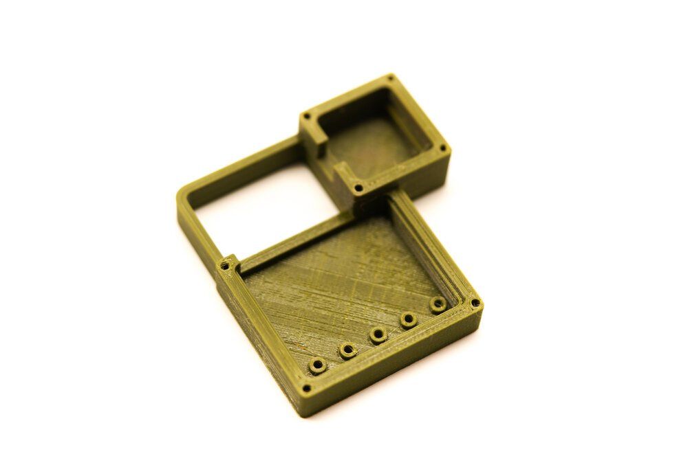
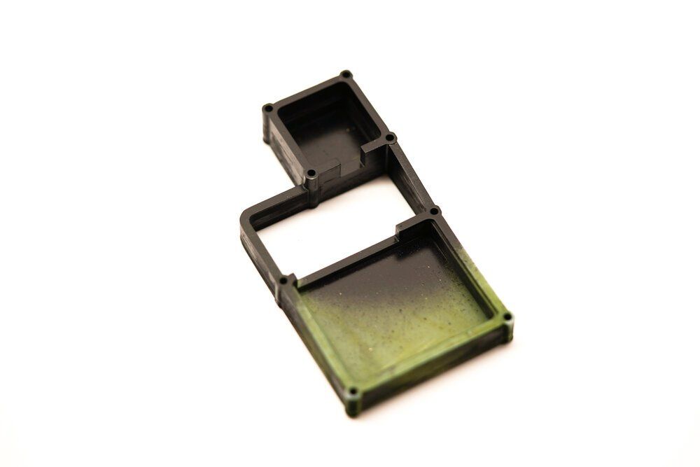
If you look below here’s a more confident version with the bottoms filled in and a shelf for both components. The GPS unit has a battery adapter on the bottom, so it doesn’t sit flush on the bottom. In this design there was meant to be a cover over the CLUE, so there’s a ton of vertical space above the board.
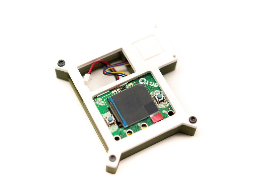
I also experimented with an SLA version, which required the GPS box to be moved- the MARS Elegoo SLA printer has a pretty tiny bed size, and I like to print flat on the bed (no supports), so it has to be a narrow part. I could not find the colors I wanted for this project, so I had to print in grey.
I did try using RIT dye from Michael’s, but it came out uneven in color, and it took 24 hours to get any real coloration. I spray painted a bit of the part to look like military surplus, and I almost wen this route- it looks pretty cool.
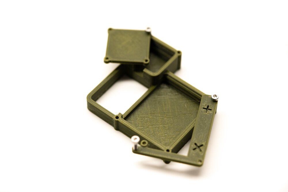
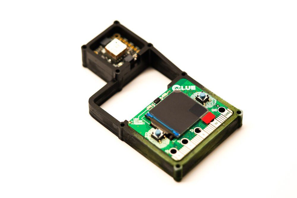
I went back to FDM plastic and I am really happy with the Military Green (link in the parts list), and here’s a shot of the panels installed but swung out, looking a little like a Swiss army knife. While the screws pressure fit OK, they felt a little fragile and the whole assembly rattled with the parts inside, so I changed my approach.
Here you can see I tried out both white and orange filaments, both of which look cool for different reasons, plus I switched over to holes that allow screws through the CLUE board to hold it in place. This approach means fewer parts to print. The variants below are minimal versions that can easily use under 20g of plastic, but they aren’t very protective of the electronics. I also added a vented back.
Assembly
Assembly is pretty easy! If you use the thicker enclosure, you will need two (2) M3 screws to hold the CLUE board in place. If you’re using the ultra minimal enclosure you only need one.
For the thicker enclosure, the screws go through the holes on the pads on the lower edge of the board- but beware- installing the screw will create problems for the capacitive touch sensors- and we need #0 and #2- but you can safely put the screws through holes for #1 and GND, we won’t be using those for buttons. Before installing the screws, carefully place the battery behind the board and turn it upside down- be very careful not to thread the screws right next to the battery or puncture it - it will damage the battery and may cause a fire. Once the battery is slide out of the way, gently thread the two M3 screws. Don’t over tighten them or you will strip the plastic or break the CLUE board.
For the ultra minimal enclosure, repeat the same step but only install a screw for the GND hole. Again, if you have the battery behind the CLUE board, be sure to read the warning just above.
The M2.5 screws are to hold the GPS sensor in place, so they don’t need to be over-tightened. If you only have two of the M2.5 screws, screw them in opposite corners. The GPS board is safe and tucked away, so it’s OK if you use only two screws, but four is fine too.
With the boards installed, carefully plug in the Stemma cable. If this is too hard, remove either the GPS board, the CLUE board, or both and connect the cable. Be careful connecting the cable, as it only goes on one way- if you force it on upside down you will damage pins on the boards.
You can simply plug in the battery when you’re ready to use it, but for programming the battery is not needed- go ahead and just plug in the micro USB cable and connect it to your computer.
Code
The latest code is always on Github here, take a look through the code- I have tried to document it pretty heavily, so it’s easy enough to modify. Make sure you look at the import settings at the top- you need to get those libraries from the CircuitPython library pack here. Some of the ones like ‘math’ are built into Circuit Python. You definitely need all the ones prefixed with ‘adafruit’. If this is your first time using Circuit Python and you’re tackling this project, check out the excellent primer on how to get your Adafruit CLUE up and running here.
Save it onto the board and change your target GPS coordinates in the code, and you should be all set!
References:
- Circuit Python libraries for the CLUE
- The Adafruit CLUE guide on learn.adafruit.com
- micro:bit physical diagram, used for modeling the enclosure
- Jérôme Renard’s great function for the compass bearing between two GPS coordinates
- Calculate the rough distance between two points (without a ton of resources used)
- Adafruit magnetometer to compass sample code
- Adafruit pinout diagram for the CLUE board
- Possible future feature- reading and writing the GPS target to storage - Adafruit reference
- Adafruit sample GPS code
Comments ()