the Kuiper Deck
Over the last few years I’ve gone through several design iterations on 3D printed, semi-portable, and Open Source computers. They usually center around a Raspberry Pi, but I’ve made that decision project by project. As I wrap up my work and focus on the cyberdeck designs I’ve worked on, I wanted to share the concept of a deck designed to go somewhere new- space.
Inspired by the rough outer asteroid belt communities in books like Seveneves and shows like The Expanse, I think that for many in the future the technology will be less like the increasingly dated Star Trek series and more like an environment where things are more utilitarian.
The idea behind this project is that it’s simply a Raspberry Pi with a better screen in a box. Often with these projects, there are compromises made, and small, hilariously low-resolution screens are used (I’m looking at you, Raspberry Pi Foundation), or they are painfully ever smaller and hard to add things on later.
Many projects are also hard to print- even my original Recovery Kit prints along the outside edge of a common 3D printer, leaving it prone to warping from temperature changes over a multi-hour print. Sadly though, while I did recently release a Quick Kit version for the Prusa Mini, there just wasn’t a good way to make this project small enough. This project has a handful of parts, which are for listed at the end of this post.
So, the most unimaginative question I continually get is “what does it do?” and the answer is- whatever you want. I’m very receptive to Cory Doctorow’s concept of the “war on general purpose computing” where companies like Dell ship BIOS that won’t boot Linux or server operating systems, drivers are limited to specific operating systems, etc. So the answer here is that as the Single Board Computer (SBC) scene produces stronger and stronger variants, you’ll be able to design a new adapter and use them in this kit.
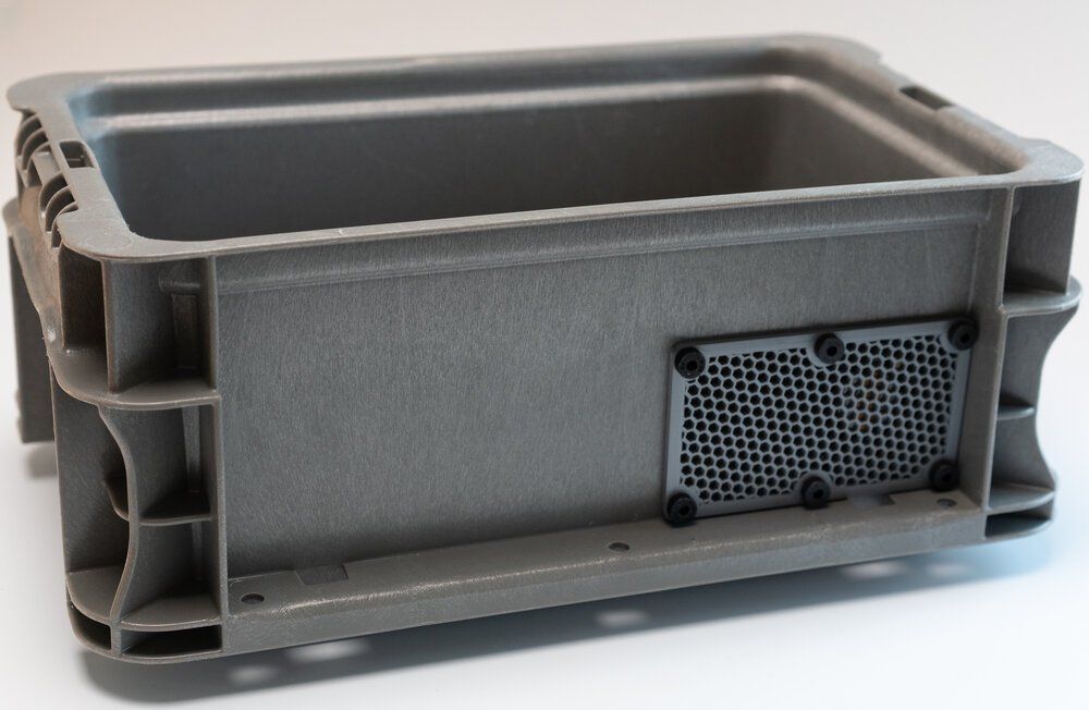
The kit centers around a humble “stackable plastic tote box” from McMaster Carr and manufactured by Orbis Corporation. You won’t get a waterproof design, but these are made from easy-to-mod polyethylene plastic, and they are much cheaper than a Pelican case- $12 plus shipping in the US, compared to $40-$50 that is common for Pelican products. The entire project pressure fits inside the bin with plenty of space behind the project, so you can add batteries, switches, wiring, custom PCBs, or pretty much anything reasonable. If you want it to be semi-permanent, a simple (and carefully placed) self-tapping screw on the sides will hold the project in place.
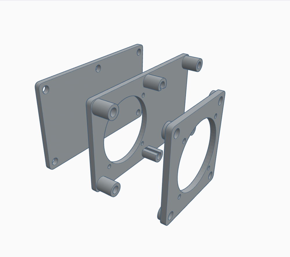
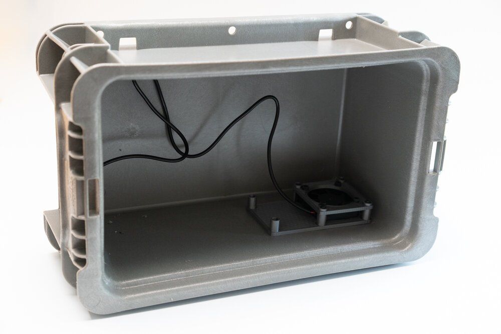
One of the other challenges was cooling- the Pelican cases don’t really leave many options for cooling, since adding a fan either takes up valuable space on the panel, or you’re adding a water ingress point when you cut a hole in your $50 case. This time I added a cheap (and admittedly a little loud) 5v fan from Amazon, but it’s low enough current that a Pi 4 can still supply fan and display voltage, keeping circuitry pretty simple for this build. I designed the fan setup to let you cut the hole in the side of the bin and use the 3D printed parts to trace the fan opening and screw locations with the part, making it easy to place it where I did and not have to worry so much about misaligned holes. You can drill out the fan hole with a power drill (I used a 1/4” bit) with a bunch of drilling around the hole, then cut the rest carefully with a box knife.
I designed the 3D printed parts for the fan to cover any mistakes, inspired by Adam Savage’s frequent term of “hide your crimes”. There are 3D printed parts that sandwich on each side of the whole you cut, so it has some room for error.
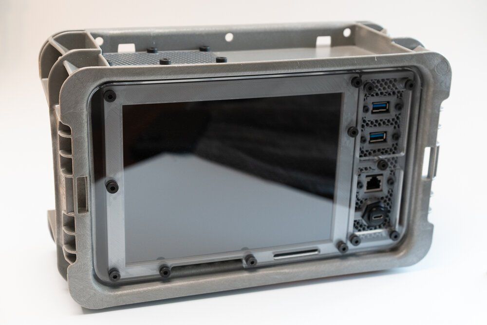
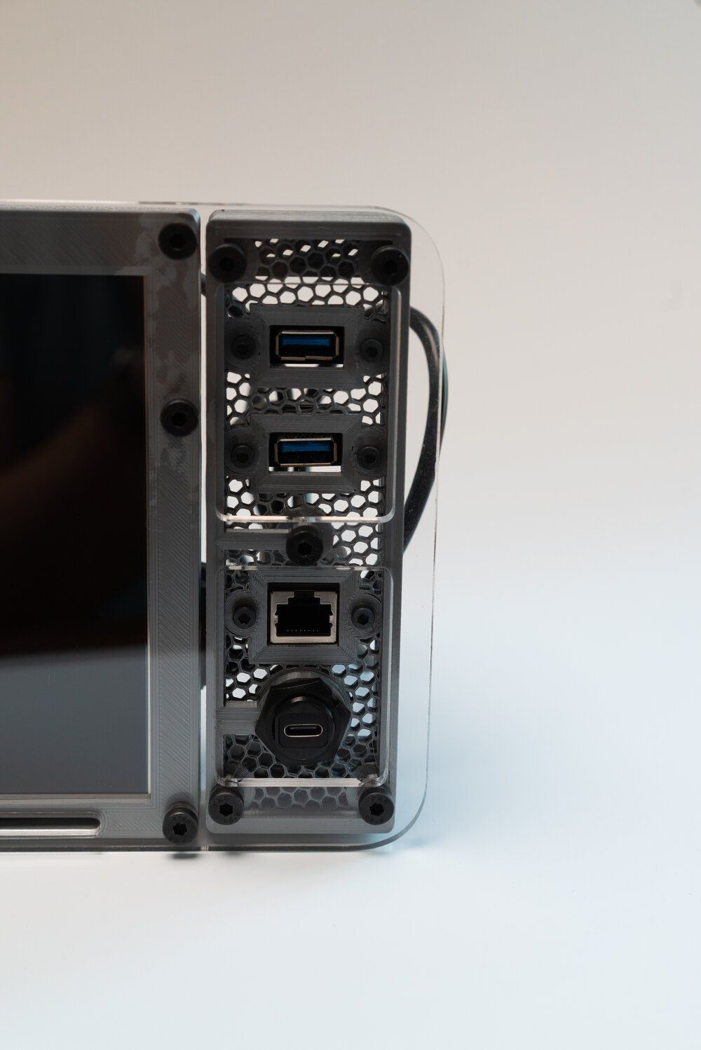
Now, with an exhaust fan you really do need an inlet for fresh air if you want the fan to do anything besides burn out and fail. While I have a small inlet just below the screen, that was meant also for random hacks of wires to be run outside the unit as well- like connecting something to GPIO without a huge modification to the case. What I did gives an effect I really like- simply set the slicer to honeycomb infill (the rectangular is faster and uses a little less filament, but I like the honeycomb), and make sure you have plenty of perimeters. For the I/O panel, I set the perimeters on the print to 10 to make sure the holes for the panel mount parts overlapped with the outside of the frame- without this the panel is a little too sensitive to twisting and can break. Then to expose the honeycomb, simply set the top and bottom layer counts to zero. You’ll want a very clean bed for these prints- they come out well, but will break up or fail to stick if you have a messy print surface.
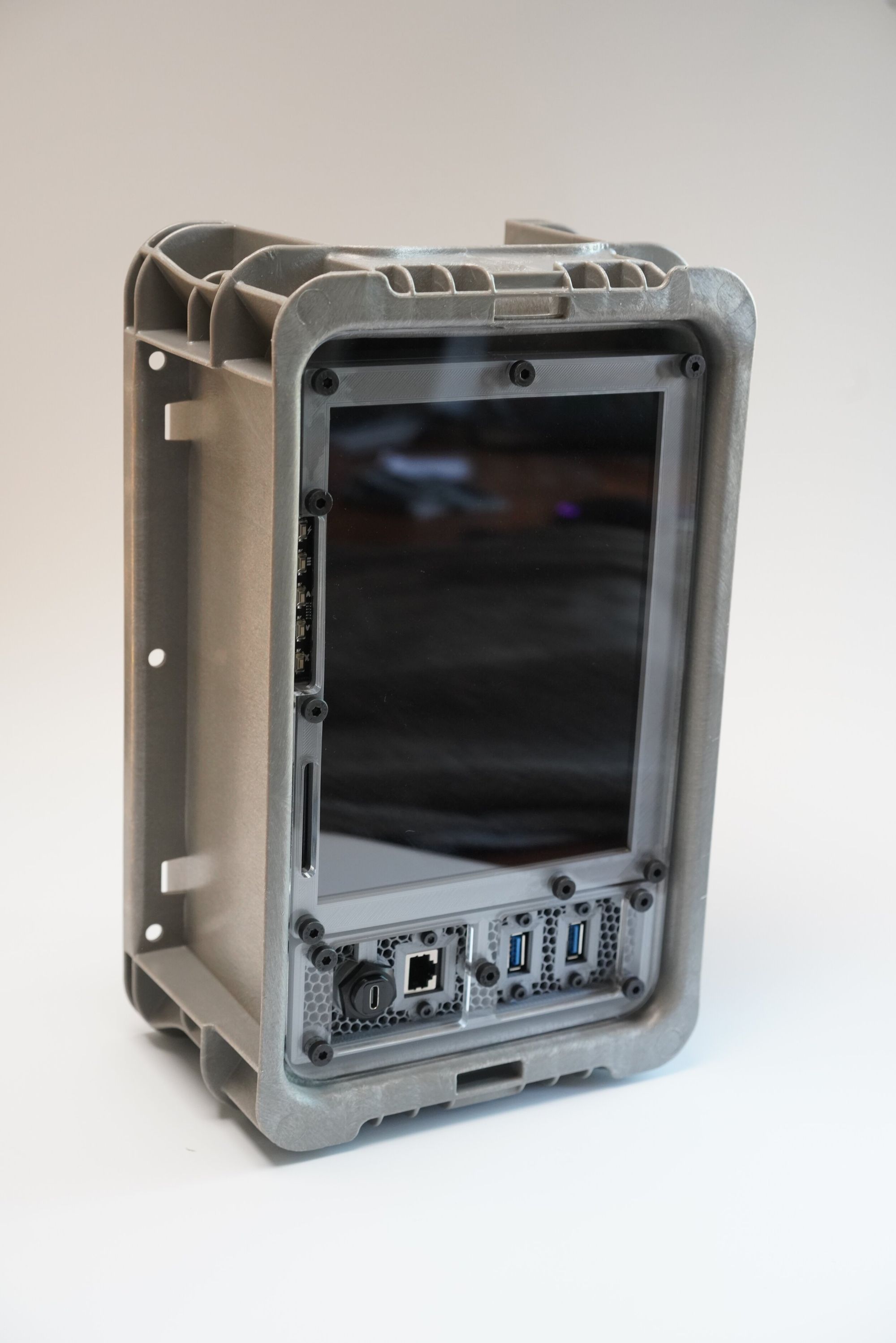
For the eagle-eyed readers you’ll notice that there’s a funny pattern where the PETG comes in contact with the clear plastic front panel- this is the same effect that would happen if we had the HDMI display directly against the plastic, so there’s a small space between. The screws to mount everything are pretty easy- M3x10mm for the panel mount USB and Ethernet, and M5x25 for the screws that attach to the clear plastic panel- nearly all of them go all the way through to the back parts. There are a handful of M5x10mm screws needed.
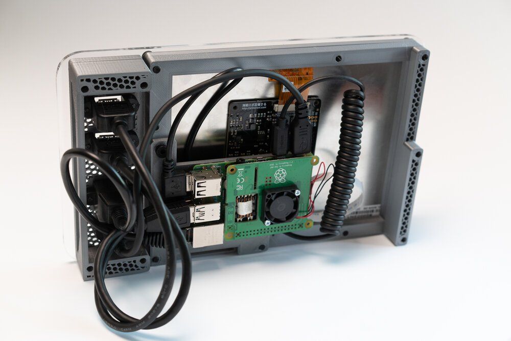
Photos below show the unit out of the enclosure- you’ll notice many common themes with the Recovery Kit and the Quick Kit, but those are simply elements that work well. The side I/O panel is separate and designed to be easy to re-print if you want to change IO. I have left several design iterations in a separate Tinkercad project here as inspiration.
What you may notice is that I have stopped using the Raspberry Pi Touchscreen display- although fairly cheap and extremely easy to integrate into projects, the resolution is just too poor for any modern usage. This project uses the Pimoroni 8” HDMI display, which can be bought at a variety of places. There’s not a ton of stock, but I think if people start building these they can get more. I don’t have pictures, but I simply applied the HDMI controller board to the back of the display with some double-sided tape. It is pretty finicky and if you get it installed right it stays there. I also exposed the button controls for the HDMI display with a small notch at the bottom- you’re not likely to fit a finger in to press them, but a pen or screwdriver works fine for me.
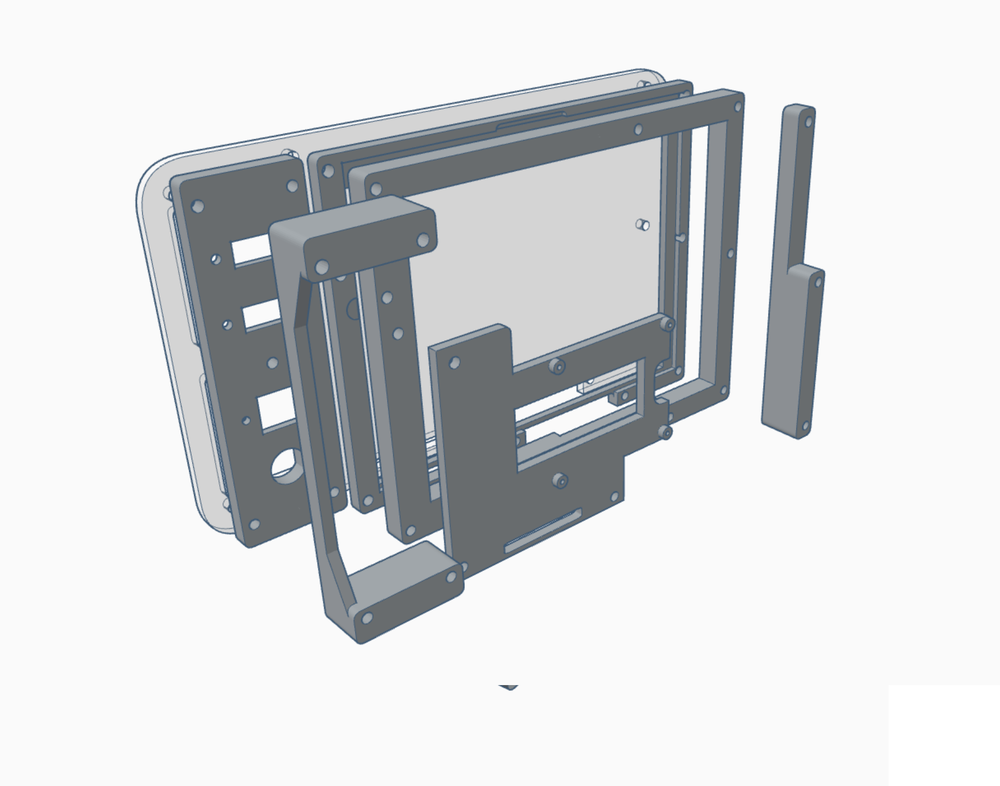
The HDMI screen sits between two parts of the plastic frame with a gap in between to allow for just the right amount of space for the screen. As I mentioned earlier, this also allows for a gap between the screen and the clear plastic front. The clear plastic front also lets me do a neat trick- it allows for me to attach multiple 3D printed parts together that would normally be too large for a normal 3D printer. In order to make this work though, the clear plastic front is 3.5mm thick- any thinner and it’s too flexible and susceptible to breaking or cracking.
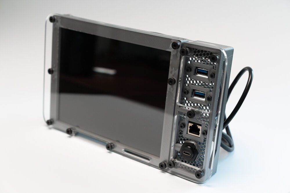
From the back you can see the wiring is actually pretty easy to do. You can see the coiled micro HDMI cord that goes from the Raspberry Pi 4 to the HDMI display. The Raspberry Pi 4 is attached to an adapter plate that is offset from the back of the HDMI panel, which allows for larger cables and also means you could easily swap out the Pi for a larger board. You’ll also notice the two parts on either side in the back- these are simply pressure fitting parts. Is your plastic bin a little too big for the print? Simply make these parts a little longer on the long side and they help keep the project pressure fit into the enclosure.
You can see I printed those pressure fit parts with no top or bottom layers- this is just because it looks neat and fits with the overall aesthetic. Next, I connect the small 5V fan if I am going to run a workload that needs cooling. You’ll notice that the fan is positioned on a corner where it’s always toward the top of the case, so in portrait mode here it vents to the right, and when in landscape mode if vents to the top. It’s a loud fan though- I had originally sourced a very quiet Noctua fan, but it pulled too much current and would require power from something besides USB. That’s for a future modification I guess.
Parts List:
- Stackable Plastic Tote Box - McMaster Carr
- Plastic Screen Guard - EPS file is on the Thingiverse Listing or for sale here.
- 3D Parts - Tinkercad and Thingiverse
- Pimoroni HDMI Display - Adafruit, Pimoroni
- Panel Mount Ethernet - Amazon
- Panel Mount USB - Amazon
- Panel Mount USB - C - Amazon
- Raspberry Pi 4 - 8GB - Amazon
- Raspberry Pi PoE (Power over Ethernet) Hat - Amazon
- Right Angle USB adapter (Power from the Pi to the HDMI board) - Amazon
- Coiled HDMI Cable - Amazon
- 40mm fan with USB power - Amazon
- M5 x 10mm Screws - McMaster Carr or Amazon
- M5 x 20mm Screws - McMaster Carr or Amazon
- M5 x 25mm Screws - McMaster Carr or Amazon
- M5 x 30mm Screws - McMaster Carr or Amazon
- M2.5 x 5mm Screws - McMaster Carr or Amazon
- M3 x 10mm Screws - McMaster Carr or Amazon
A few final thoughts on this series of “cyberdeck” designs. Although I read (and loved) William Gibson’s Neuromancer, I set out for these projects to be durable, portable, and hackable Raspberry Pi designs. While I’m not swearing off or stopping cyberdeck work, I think it’s time for me to focus on other projects for a while. I will be sharing some incomplete designs on Tinkercad later this month with the hopes this project and my remaining designs are helpful to others. I will continue to sell kits as long as I can, but this is not goodbye- not for cyberdecks, but mostly for Tinkercad. The projects I release this month are the last of my Tinkercad designs while I transition to Fusion 360. Thanks for reading and following along!

Comments ()