Recovery Kit Retrospective
In celebration of all the new subscribers, I thought I'd share some behind the scenes photos of 2019 and 2020 from the build of the original Raspberry Pi Recovery Kit, including some commissioned builds. Future projects will be shared like this for paid subscribers, but don't worry- free subs will always have access to the build and design files.
There are two paid tiers- the $3/month tier that is also $30/year, and the $20/month tier which will be going up in the fall. Both are great ways to support future projects, but also a great way to interact with me and the group in general. The higher tier gets you some neat stuff like the ability to request design changes on projects.
Anyway, on to the build photos!
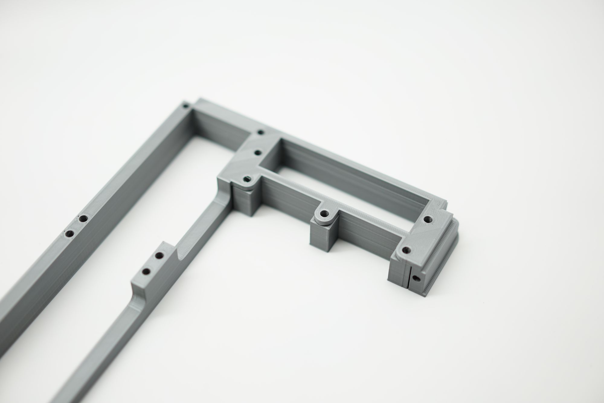
The earliest version had me trying to figure out a bunch of stuff all at once- the radius of the corners, the layout for the components, and even general hole spacing. This photo had the keyboard kind of close, but the final one looked very different. Printing the main frame for the Recovery Kit was tough on the Prusa MK2 - that printer can be really picky when printing close to the edges- making print failures more common than I would have liked. It really comes down to a narrow range of where your print/plastic is- and the center is a popular spot for printing for a good reason.
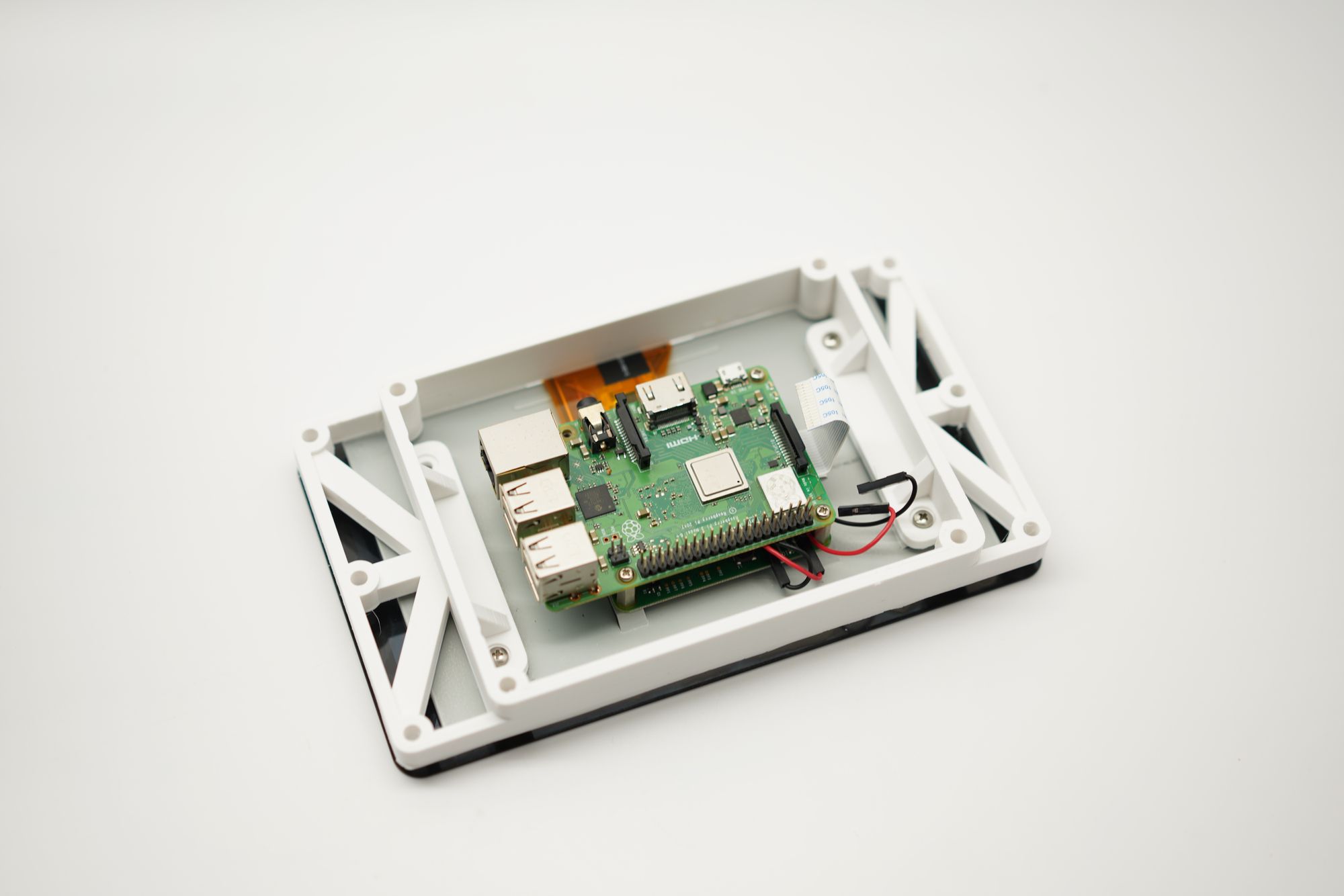
I didn't capture many tests of the display frame, but it was pretty easy to dial in and a part I've changed very little since then. If I had my way, the screw holes for the frame would be centered left/right and top/bottom, but as they are now the mounts for the display are offset just a little bit. Also, if your screws are too long, they go into the back of the display!
This part let me deal with the different heights/depths of the display and easily get it mounted to the frame without a ton of supports. With the Quick Kit I made this far simpler, but this part was pretty reliable- but probably overbuilt.
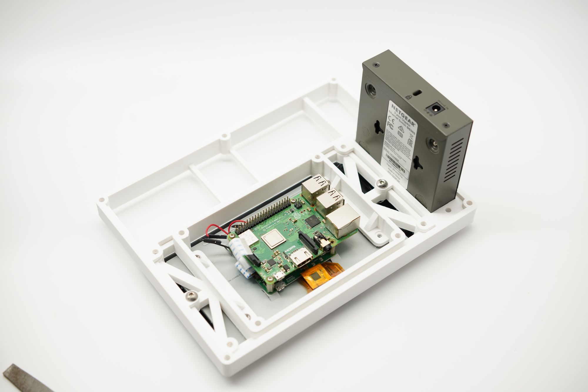
Still printing in white for the test prints, you can see the display frame mounted to the main frame, plus the Ethernet switch mounted in. If you look close you can see the area where all the connectors and toggle switches will go- it's all just some simple supports. I'm a big fan of incremental testing, building one bit at a time to keep it simple- layering on each time with more detail.
I am no fan of printer supports, and I came up with this on my own- but it's not a new idea. I used these little rectangular blocks as sacrificial parts to support the mounting tabs for the display bracket. The blocks each had a small hole in them, making them easy to snap off with a screwdriver or needle nose pliers.
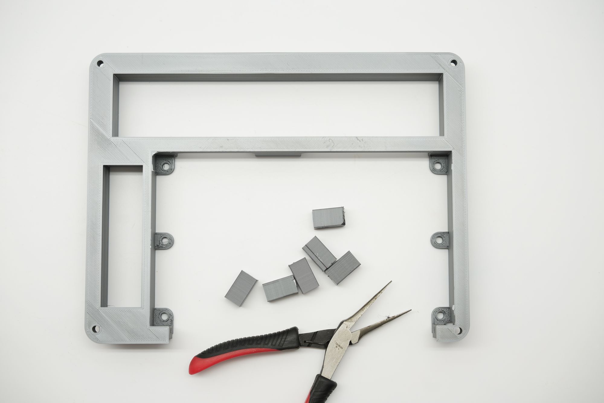
If you look close you can see these actually break off quite clean, and all I really needed to do was leave a sub-1mm gap to make a weak layer between the sacrificial block and the print.
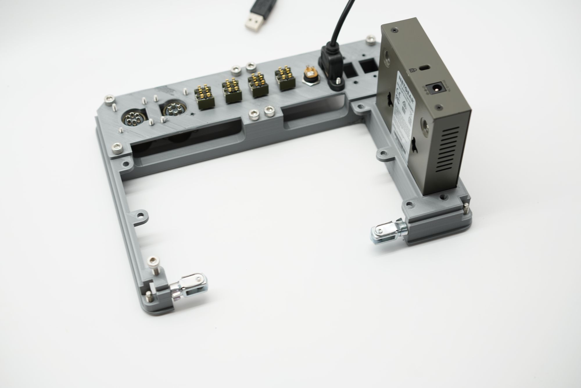
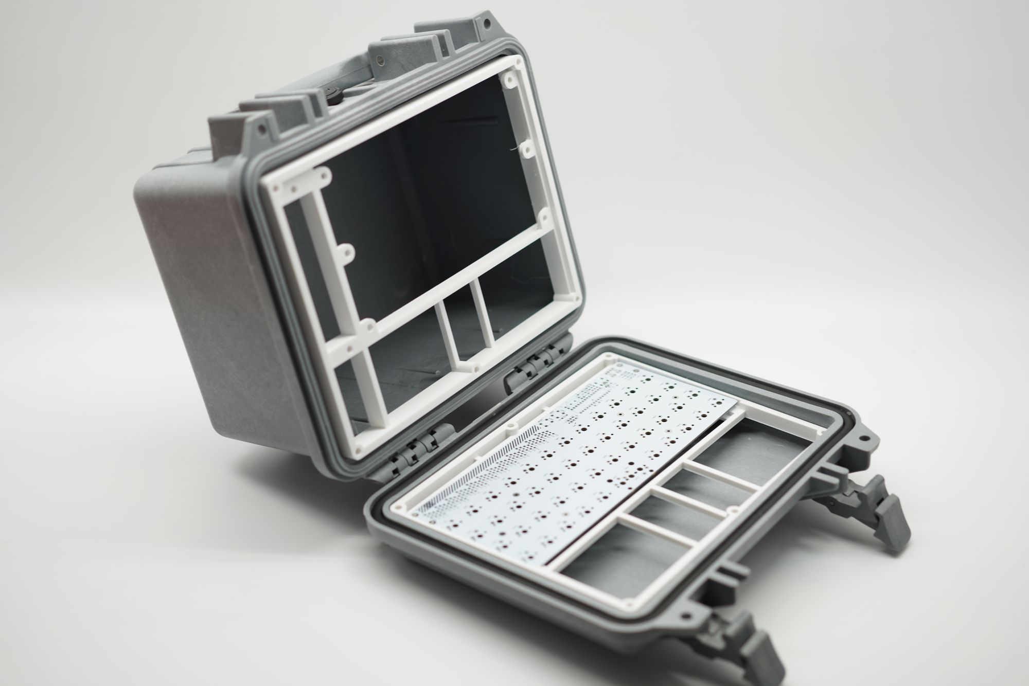
In this photo you can see some of my favorite features and some of my least favorite ones too- the clevis pins at the bottom of the photo had a wire routed between them for a handle. The pins ended up creating issues later- they had a habit of rotating and binding with the Pelican case, putting pressure on the frame and cracking it over time- the pins looked neat, but they're not a feature I'd add today.
However, I am very happy with the vents! The area where the clevis pins were acted as the top vent, and the inlet vent was just below the display and above the switches and connectors. This didn't really show up on the main photos I shared, so I had quite a few questions on cooling. These vents seem to do fine- I haven't had any issues with heat buildup with the Recovery Kit.
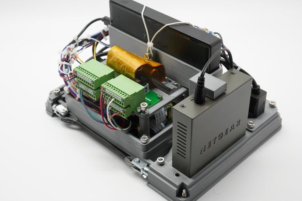
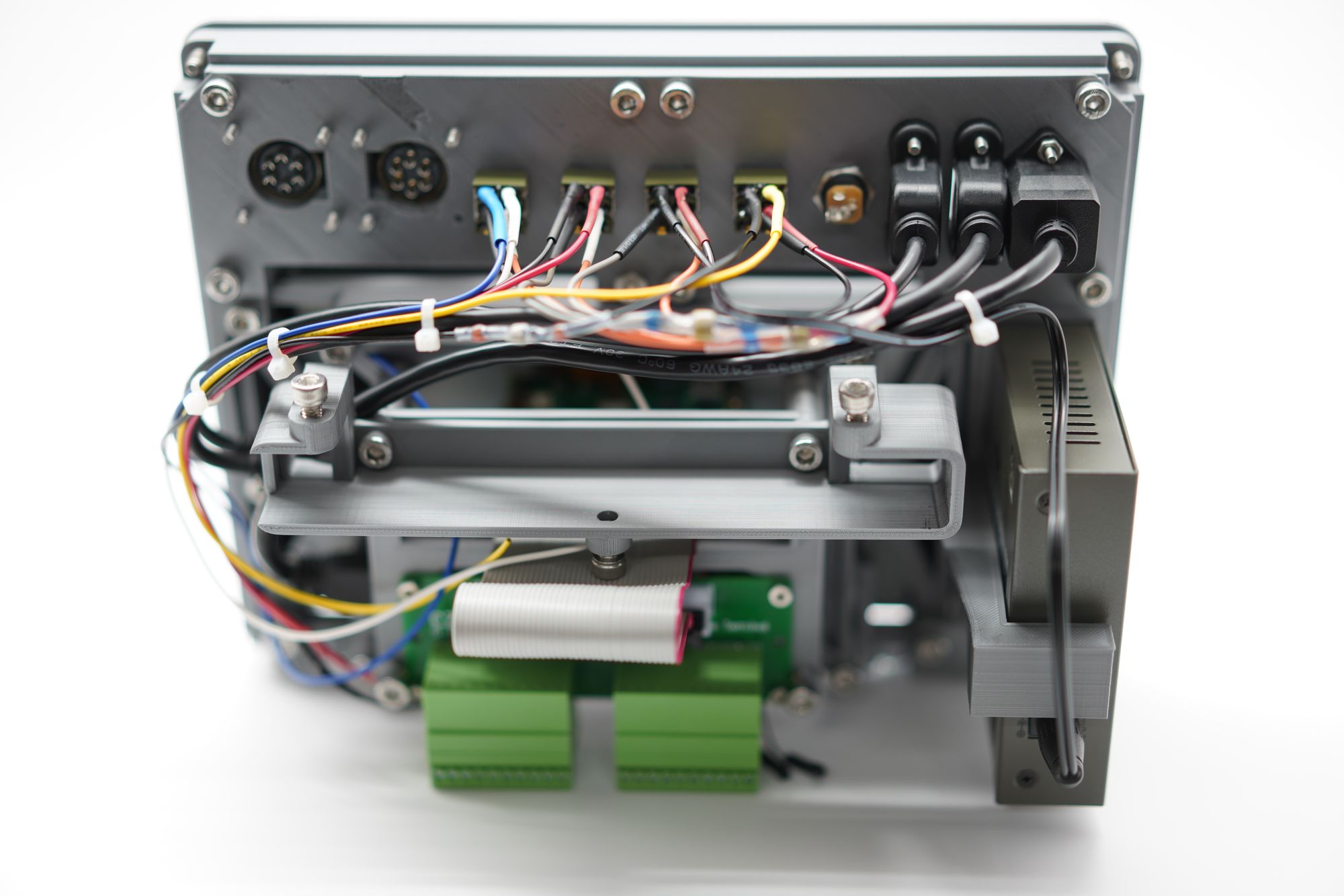
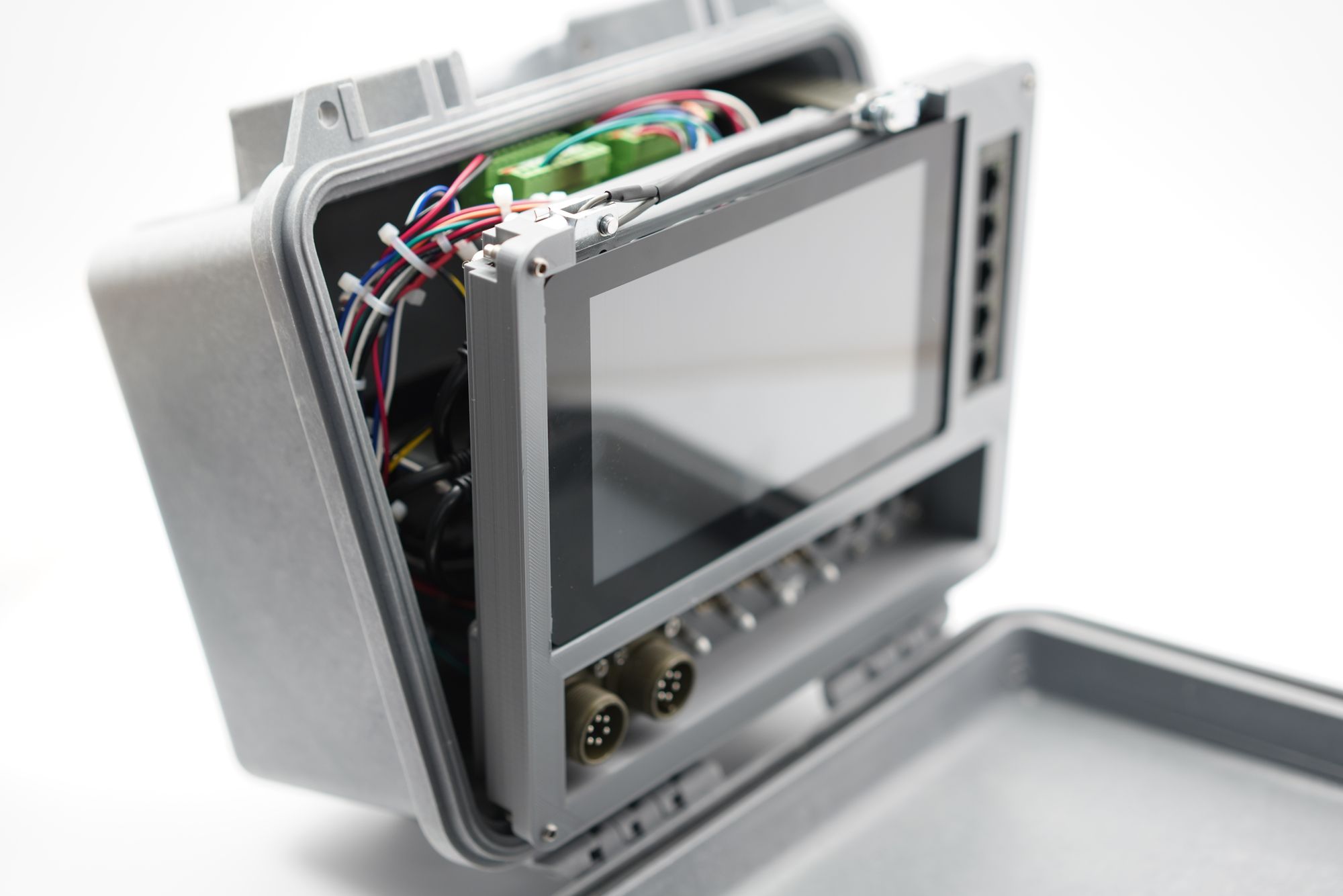
I have mixed feelings about the wiring - you can see just how many connectors there were to solder in the photo above, and the start of the wiring in the photo below. I enjoyed wiring it, but it also made building these for clients very time consuming. While I still do commissions occasionally, many people that don't do this kind of work are surprised how much time and effort goes into custom wiring and soldering. There are over 30 individual solder connections for wires, which are a bit harder and slower going than through-hole PCB soldering.
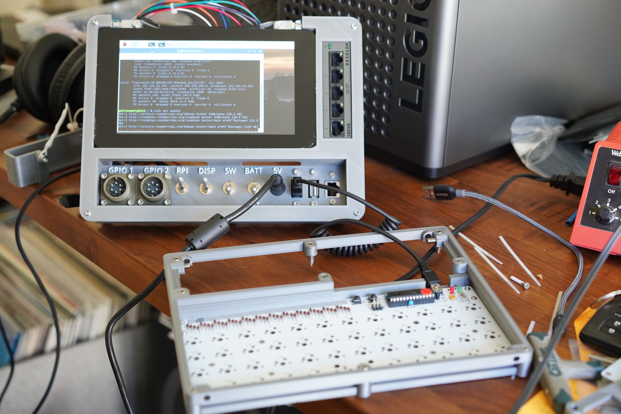
After wiring up the unit enough to start testing components, one key area was getting the Plaid keyboard kit to work. At the time none of the online configurators for the keyboard supported this model, and the AT chip used for the keyboard was shipped without being pre-programmed. As a result, the tools for flashing, loading, and programming the keyboard were all build on the original Recovery Kit. Even future keyboards for commissions were flashed on the original Recovery Kit.
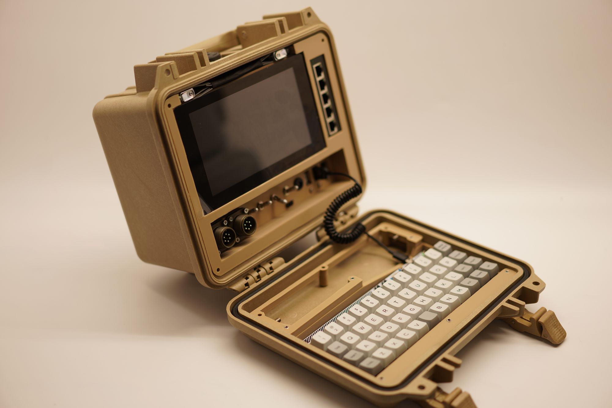
I found it really satisfying how the parts all fit so snugly into the Pelican 1300 case. You can see those devilish clevis pins, but I was really happy out it turned out.
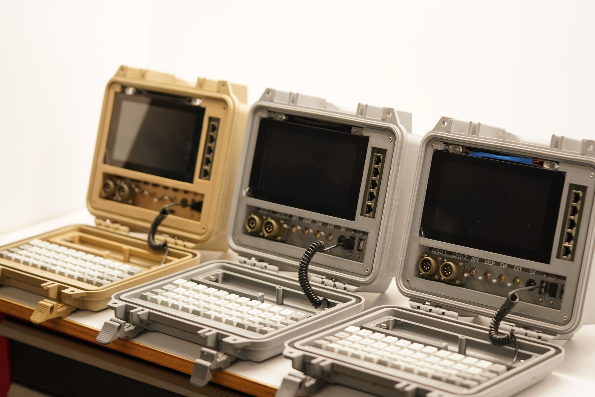
Now for some photos of the early commissions for a client. This includes the rare tan one, which two of which were only ever made by me.
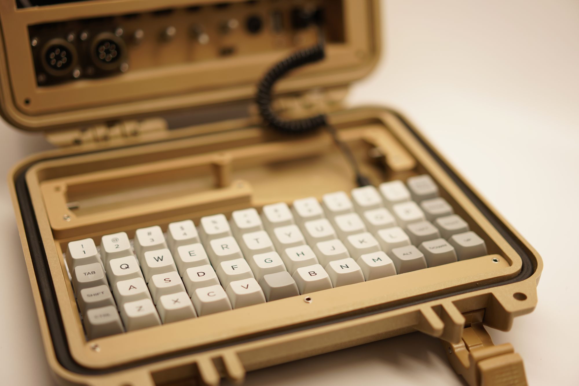
The tan has a special place for me, and really ties into that monochromatic look I like so much.
Lastly, a family photo below of my first three commissions- I am grateful to the client for giving me a chance to build for them, and happy to know they're out there in the wild somewhere!
Thanks for taking a visit to look at these old photos with me! I will continue sharing behind-the-scenes photos of other builds, but those will be for subscribers only. I expect to have the initial designs for the new build starting in August, and those details are for paid subscribers only. Thank you to all who have signed up and are supporting the new designs!
Comments ()