The Recovery Kit Ultra
Sometimes you need more than a Recovery Kit Nano, more than the Recovery Quick Kit, and even more than the Recovery Kit 2. What started as a project to get a 19" rack into a Pelican 1607 Air ended up with a very modular, very DIY, and very over-the-top PC build.
The series of Recovery Kits started in 2019 for me, with some of my earliest projects going back even earlier. Each Recovery Kit until now has been based on a Raspberry Pi, the little board that has powered so many cyberdecks. I had often wondered what a full PC build would like. For many PC users, the Raspberry Pi and Linux in general can be daunting, but the beauty of the general purpose computer is that you can use it for just about anything.
The Recovery Kit Ultra is meant to be more than just a computer. It's meant to be a Mostly Portable system that acts as an anchor for a standalone network as well as a full functional PC. There are a number of components that go into this setup- and it makes for a pretty chunky system. This took over a year part time to develop and build, so the design files are available here via my Ghost subscription.
As you read below, I hope to give you a thorough tour of the hardware build with a system that is not only 100% custom, but also available for you to build and modify.
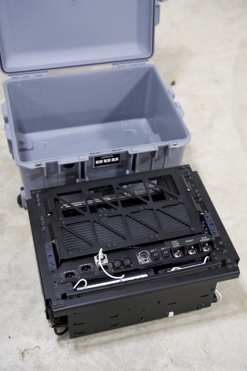
The Pelican Case
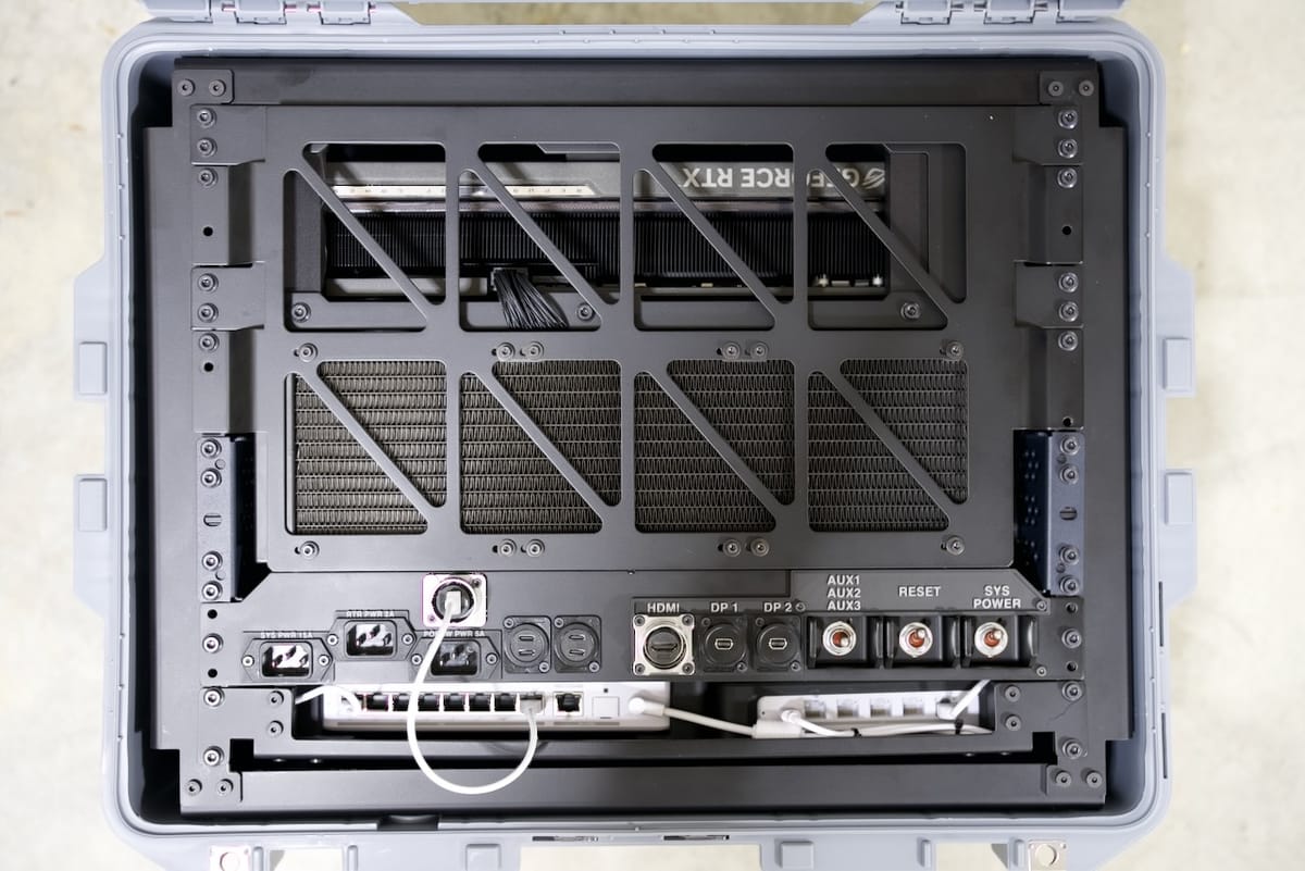
One of the signature parts of many of my Recovery Kits is present here, with the Pelican 1607 Air. While quite a bit larger than any case I've used to date, this is one of the lighter offerings and is a protective shell on this project rather than a structural element. The weight of the components here is too much for simple pressure fitting, since the mass of the. unit could let it slide out of the frame if left on its side. I've preferred to simply use the case here for transportation- the thermals could work under light loads with the lid open, but I don't recommend running the system in the case. As you'll see next on the frame, there are M5 mounting screws on all sides, so if you were willing to give up the watertight qualities of the case, you could mount the Recovery Kit to the case.
Additionally, you might notice the absence of a battery- I continue to think that rugged systems need dedicated batteries. This time I've also omitted the keyboard and screen as well. This puts this device somewhere closer to a desktop PC- and that it is. We'll get to the electronics in a bit.
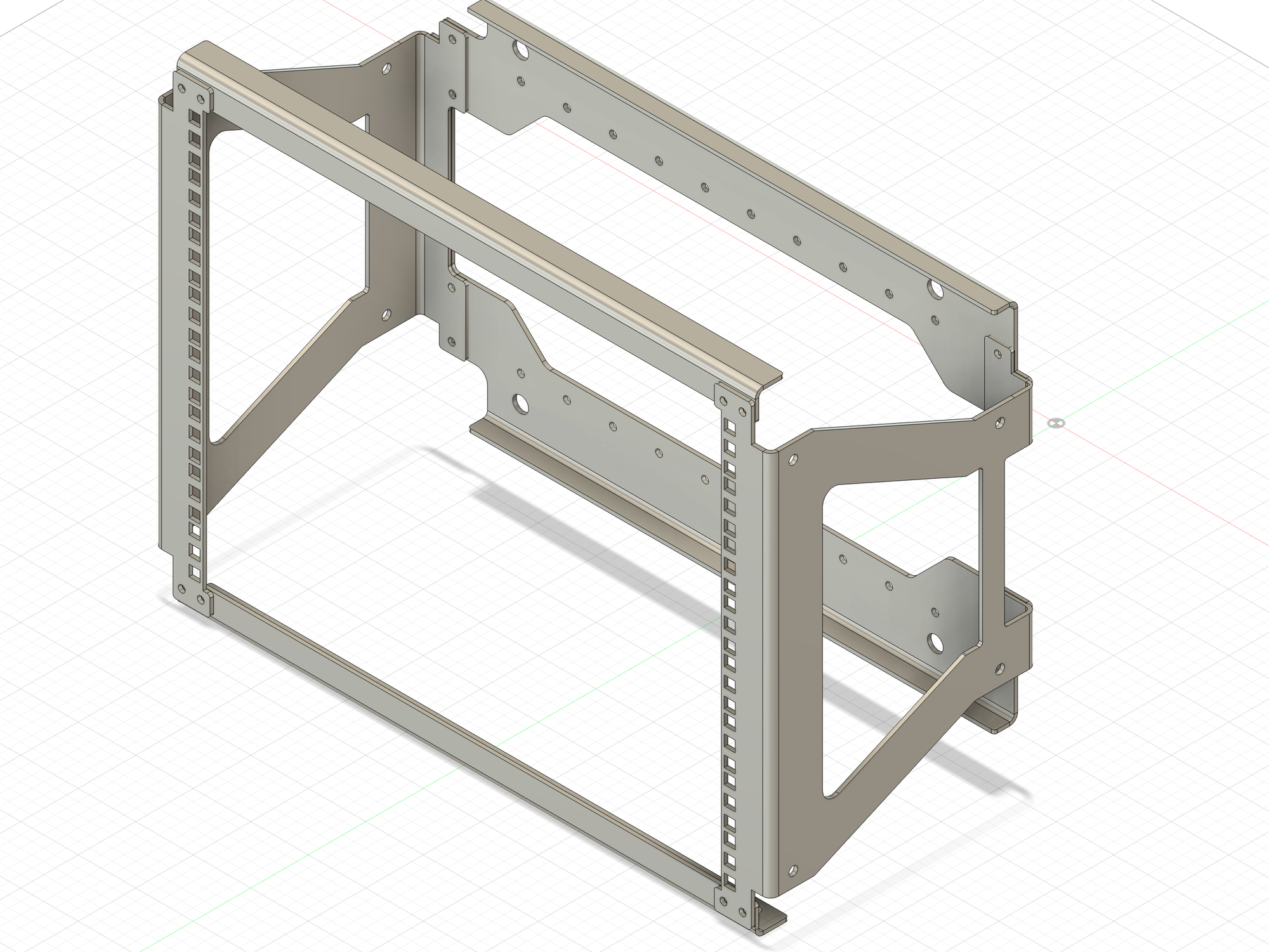
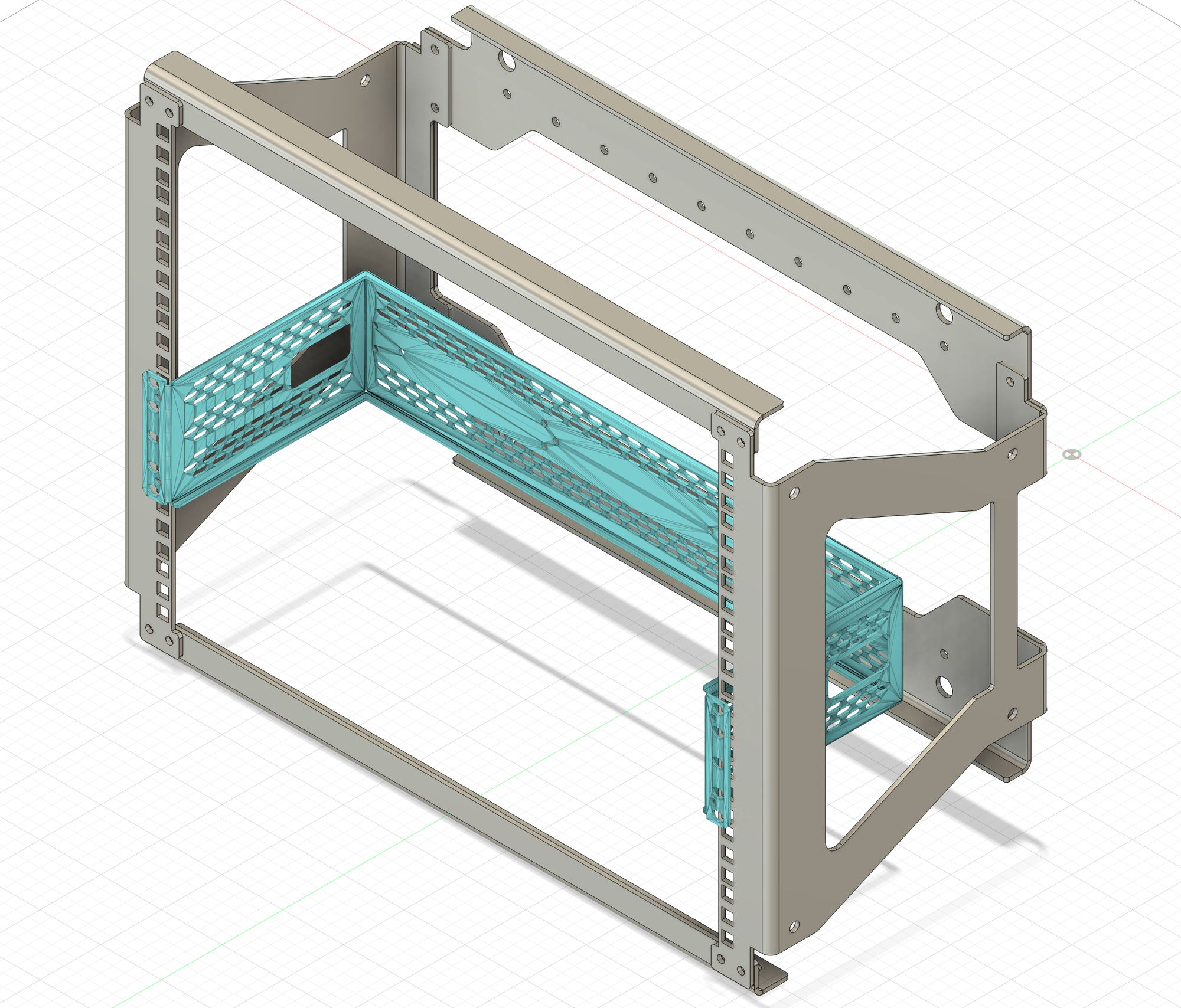
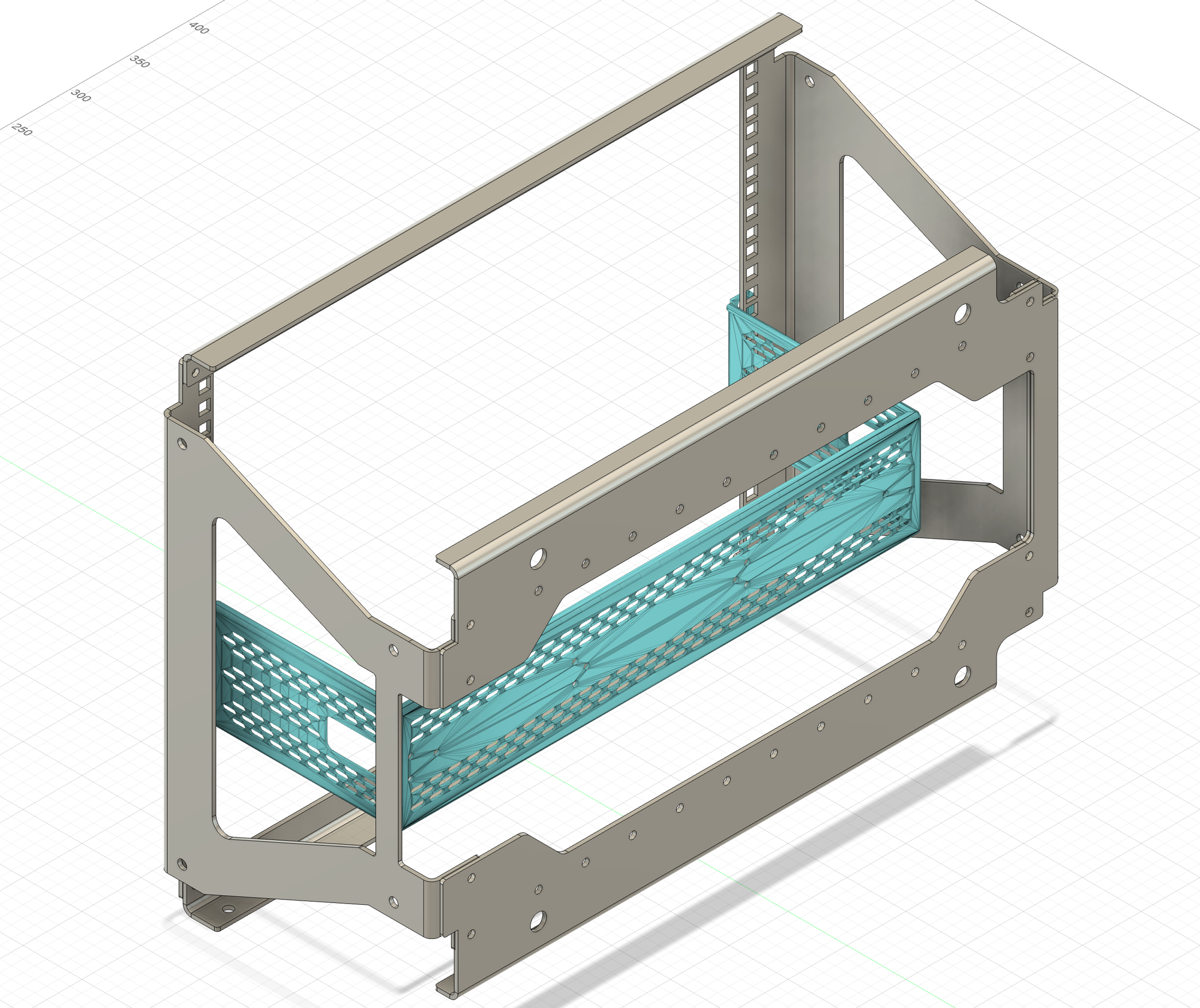
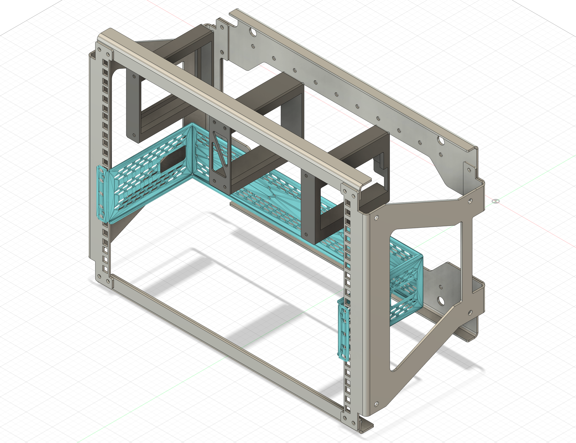
Core Frame
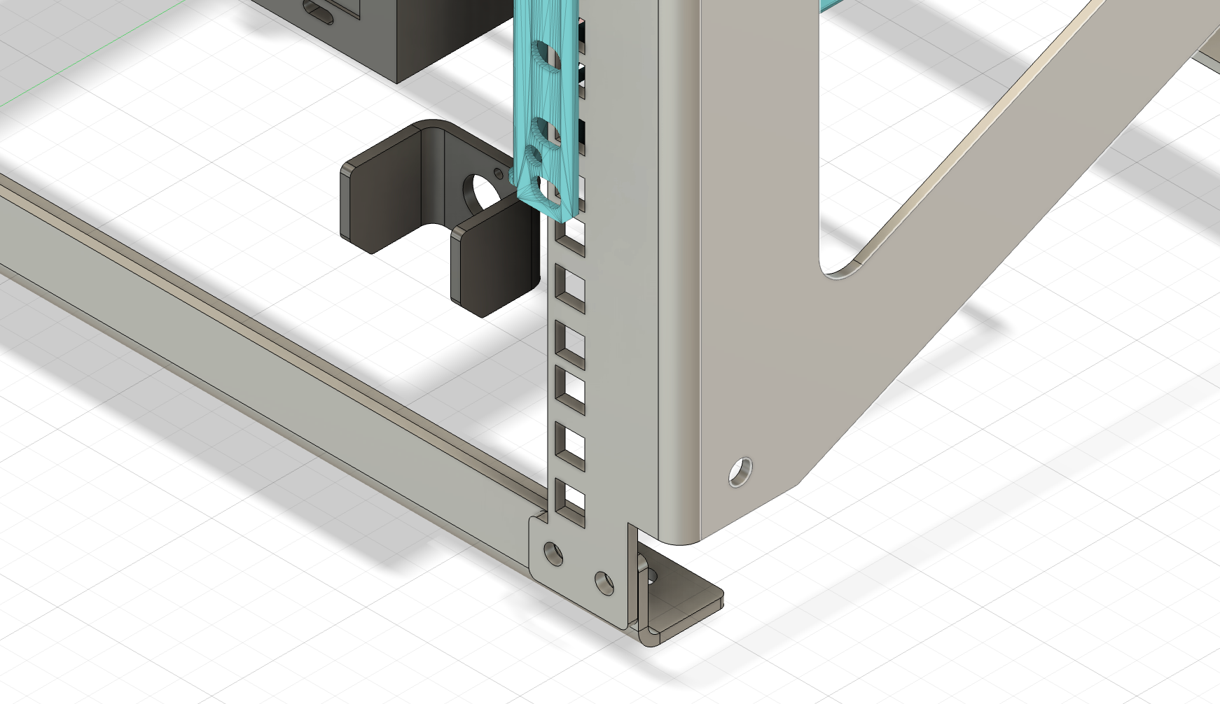
The core frame of the Recovery Kit Ultra is made from powder coated 5052 H32 Aluminum (0.125"). The bends give it strength from flexing, giving us a quite reasonable frame to work with. There are threaded mount points throughout, including the sides and bottom of the unit- which is where the SFX power supply for the build is located. The bottom screws are spaced along two lines, as well as the corners. The corner holes are where I've had threaded holes for rubber feet installed. Everything besides the power supply mounts to the standard 19" rack. Due to the design decision to go with aluminum, the 0.125" thickness plus the powder coating makes the rack squares a bit too thick for traditional rack nuts. You can use slide-on nuts just fine, but instead I opted for my own custom 3D printed nuts for now, which may get CNC'd in the near future. For now, the system has worked quite well with 8U of shallow depth rack storage usually geared more towards shallow depth audio or networking gear. This outside frame has identical top and bottom front bars, with a 90 degree bend for rigidity. The bottom is a single part, plus the two sides. The two sides are not identical to work around the spot in the case where Pelican put the integrated case handle. Each part has several threaded nuts inserted by Send Cut Send as part of their parts fabrication. (Send Cut Send has not sponsored this build)
DIN Rail and the Heart of Modularity
The DIN rail is traditionally used for PLC and other industrial equipment, and was a key "discovery" for this build. Adding the DIN rail to 19" rack adapter showed me how I could mount the motherboard, which up until then looked like a very complex and expensive part to prototype. Knowing what I know now though, I would probably just make my own rack adapter and include all the mounts I need for things like the motherboard, PSU, etc. There is "room" for more optimization and reduction in part count around this, especially if I plan to use it only for this PC, but again with this system being modular, I can redesign as much of this build for whatever I may change my mind on later.
Keep in mind there is not much space left over after adding the 360mm water cooler- the radius on the hoses, the water pump, CPU block, and the three 120mm fans eat up nearly all the extra room.
That said, the DIN rail means I could pop out the motherboard and cooler and drop in some DIN-mounted Raspberry Pi's pretty quickly. I don't see this build going back to a Raspberry Pi, but the modular nature of this build is the core idea. Swap out the GPU for 3.5" hard drives? Just replace the GPU bracket. Take out the water cooler and ITX board and put in an ATX board? Just make a new motherboard mount.
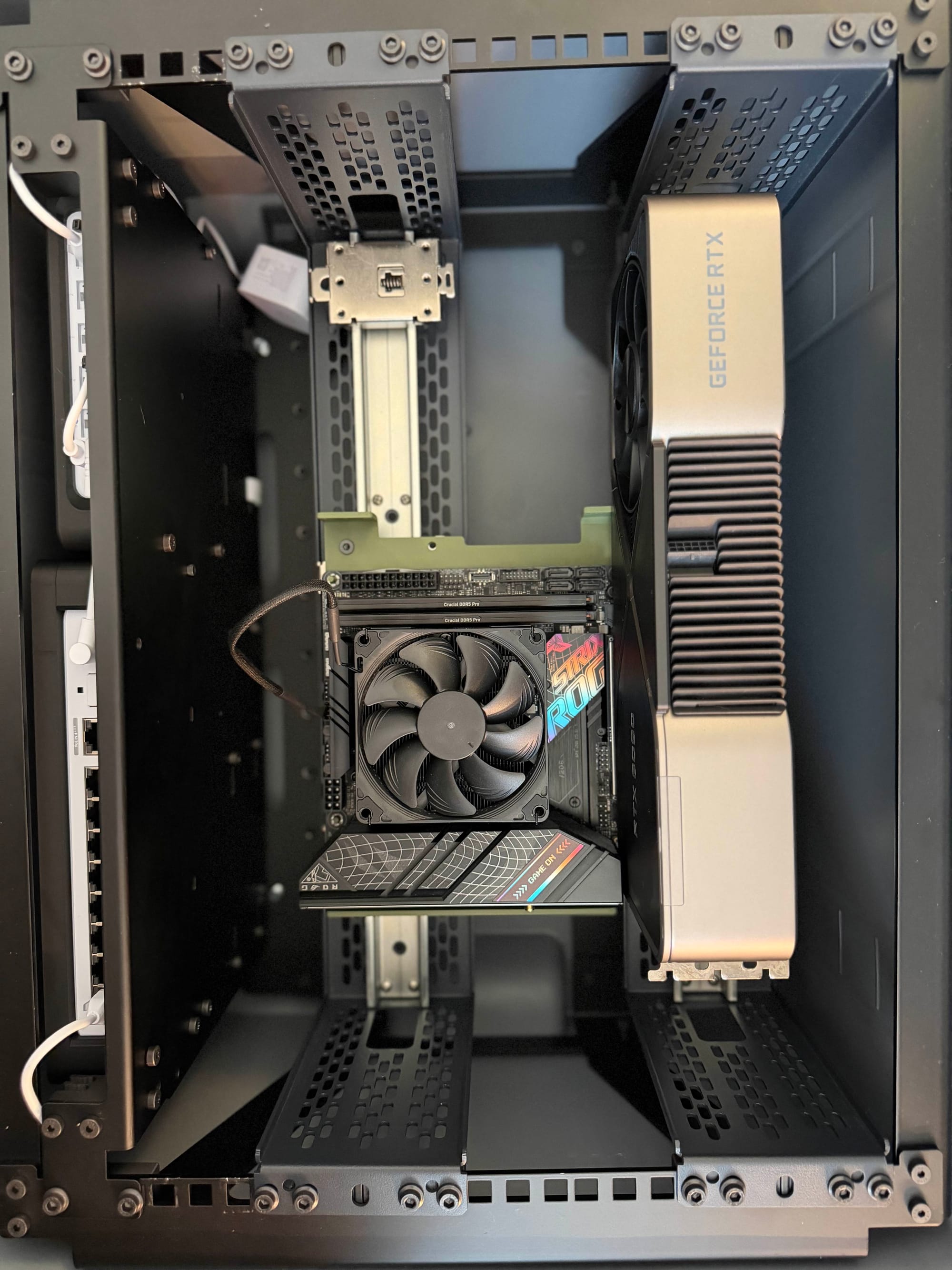
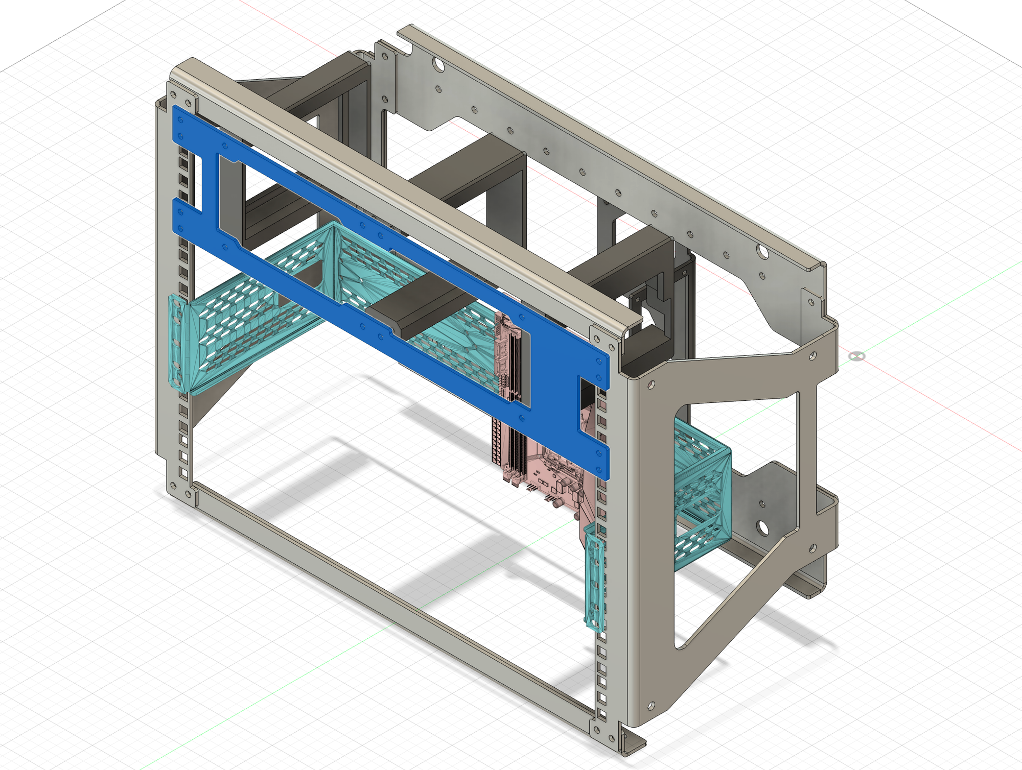
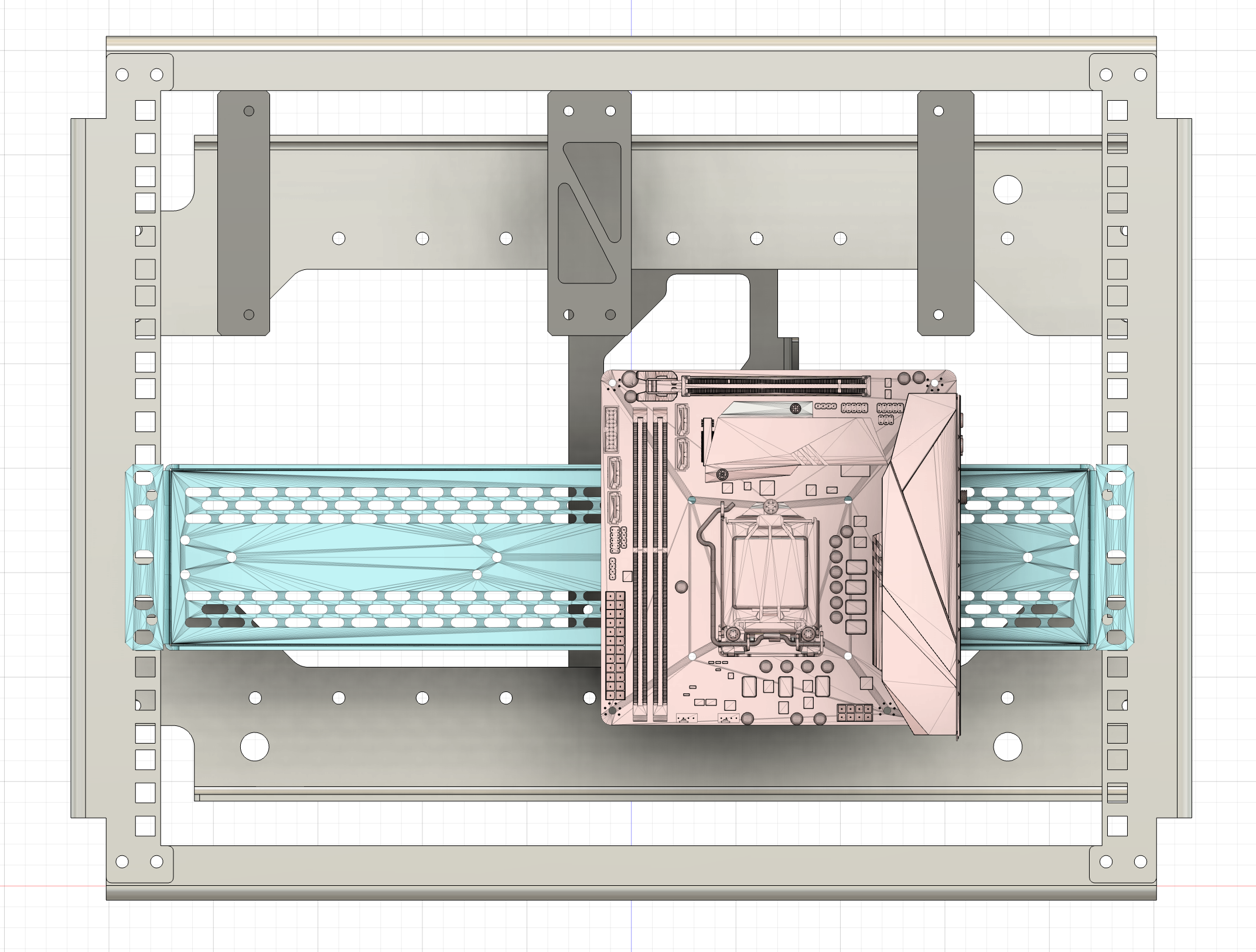
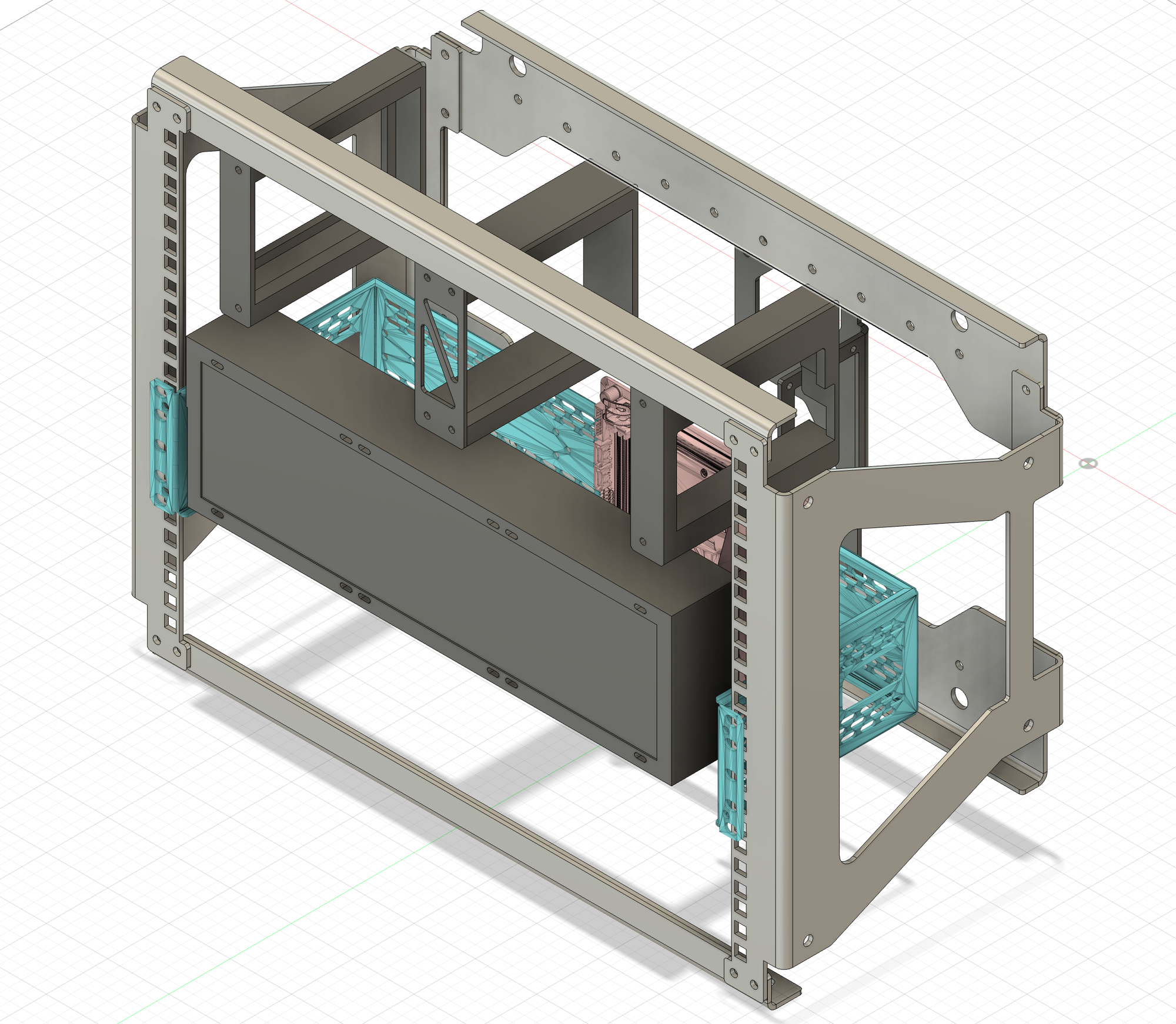
You can see in the photo below a 3090 as a mockup and a 3D printed plate for the mockup motherboard. The original design considered a second DIN rail, but the cage for the GPU made the second rail unnecessary.
Unlike the traditional PC case that can really only be a PC case, you could put radios, sensors, storage, or just about anything in a nearly endless array of configurations- as long as they fit in the limited space here. A second DIN rail and other components could always be added back- this is the core idea behind this case and this system.
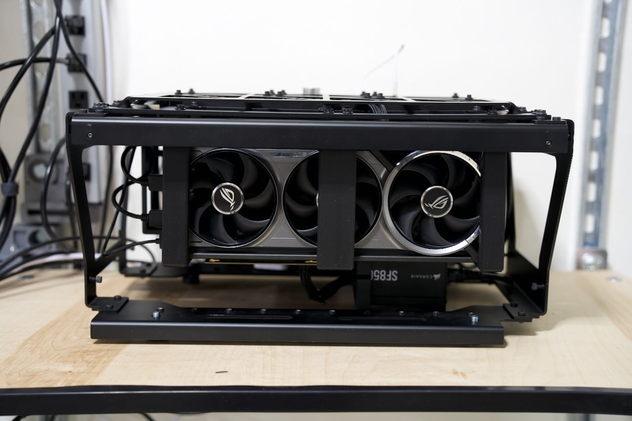
GPU Considerations
Without putting it on a scale, it's easy to say the included Asus ROG RTX 5080 is over half the weight of the components. This created several challenges for this build.
First, the sheer weight creates a risk for the motherboard PCI-E connector, so I needed to either make sure the GPU and motherboard always moved in unison or the connection between the two needed to be flexible. If I designed the CPU, motherboard, and GPU as a single unit, it would be less modular, and frankly even more complicated. Instead, I used a simple GPU riser cable to connect the GPU to the motherboard. This solved the issue by allowing me to build a frame around the GPU and connect with the riser cable. This lets me install the motherboard, then install the GPU, then connect them once they are both secure.
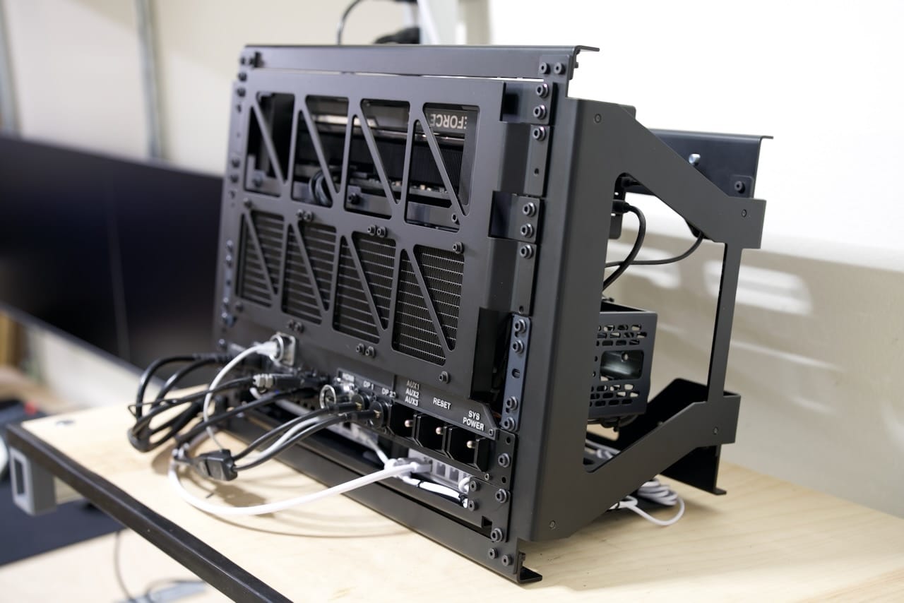
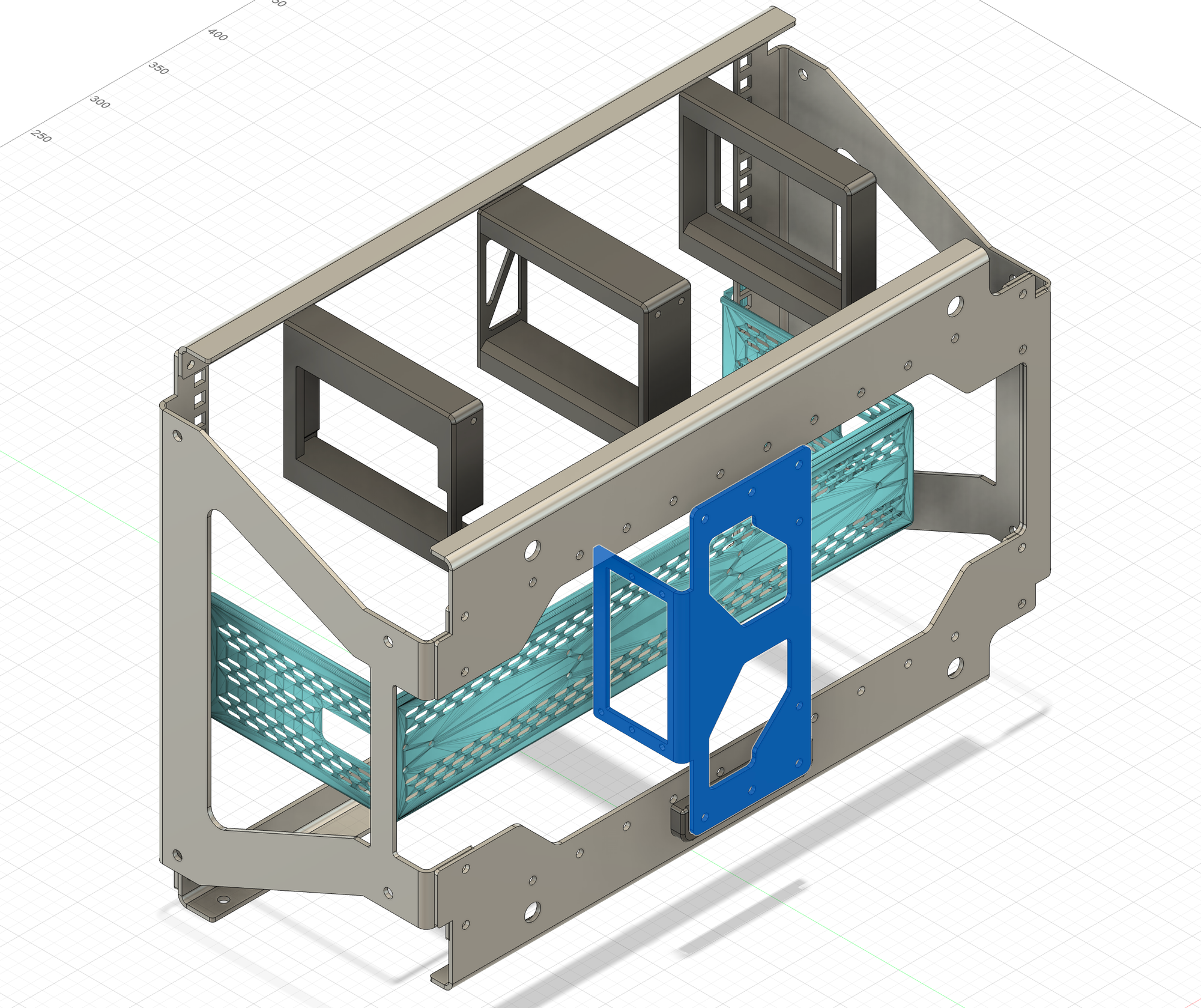
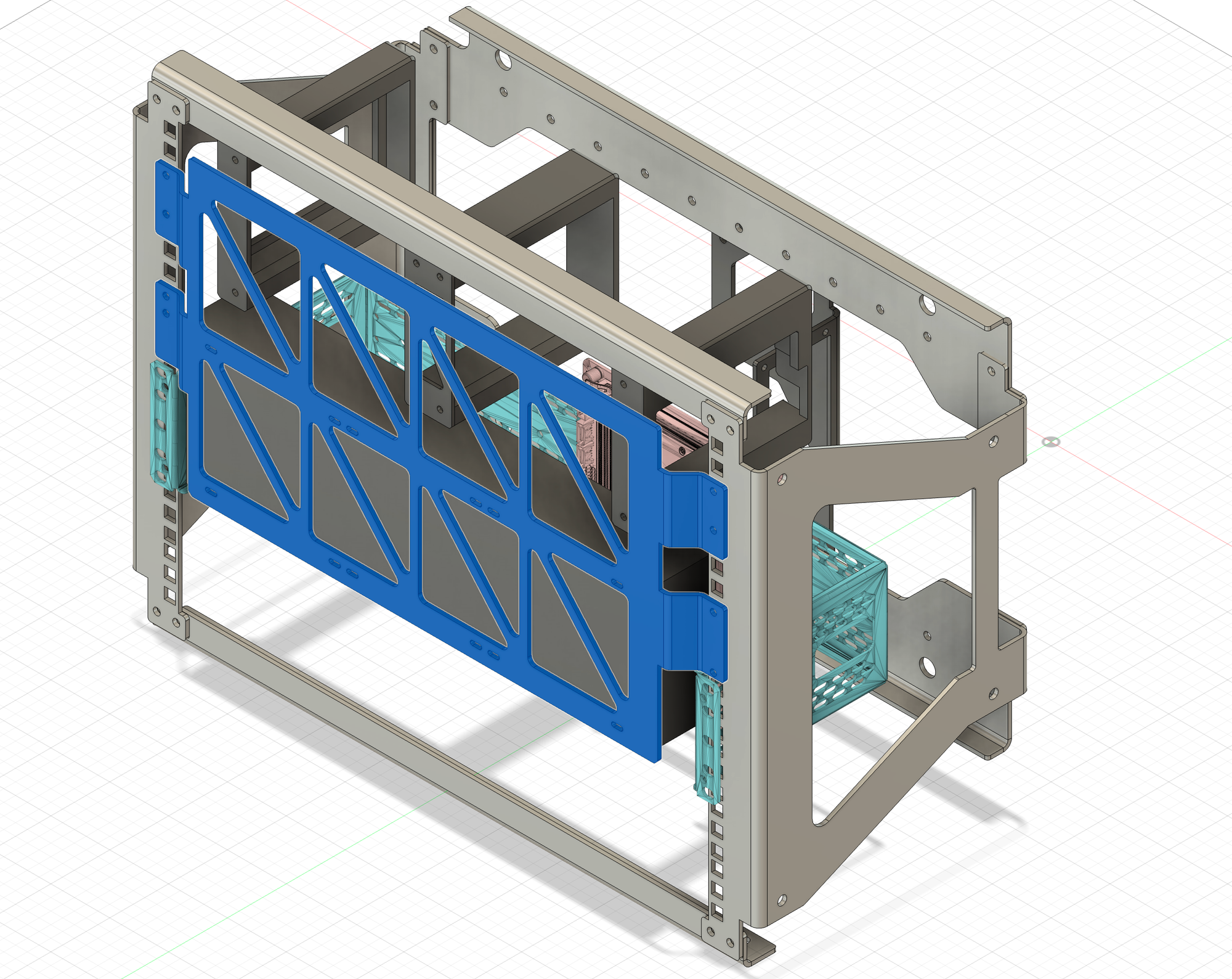
Second, the frame I built around the GPU needed to give max airflow, so with some PETG parts I created a sort of "crate" around the GPU. I removed the expansion cover plate from the GPU and kept it as open as possible. This frame has a metal front cover you can see under the triangle grill. With this approach I can redesign a new GPU crate for a different GPU in the future, but at this point I doubt a larger GPU would fit- not to mention the escalating power requirements of larger GPU's.
The entire GPU bracket assembly is a middle support and two opposing endcaps tailored for the ASUS ROG 5080. In order to make it work, the expansion slot cover for the GPU has been removed. The entire assembly mounts to a front plate, making it surprisingly easy to remove the GPU:
The GPU has plenty of depth available, and for another GPU like a reference series, it could pretty easily fit, maybe even with just some modified printed parts. Since the power connector for the GPU comes out of the "top" of the card towards the face of my build, the GPU needs to be recessed a bit to allow that cable to safely bend. Otherwise, the GPU would be far closer to the front grill on this build.
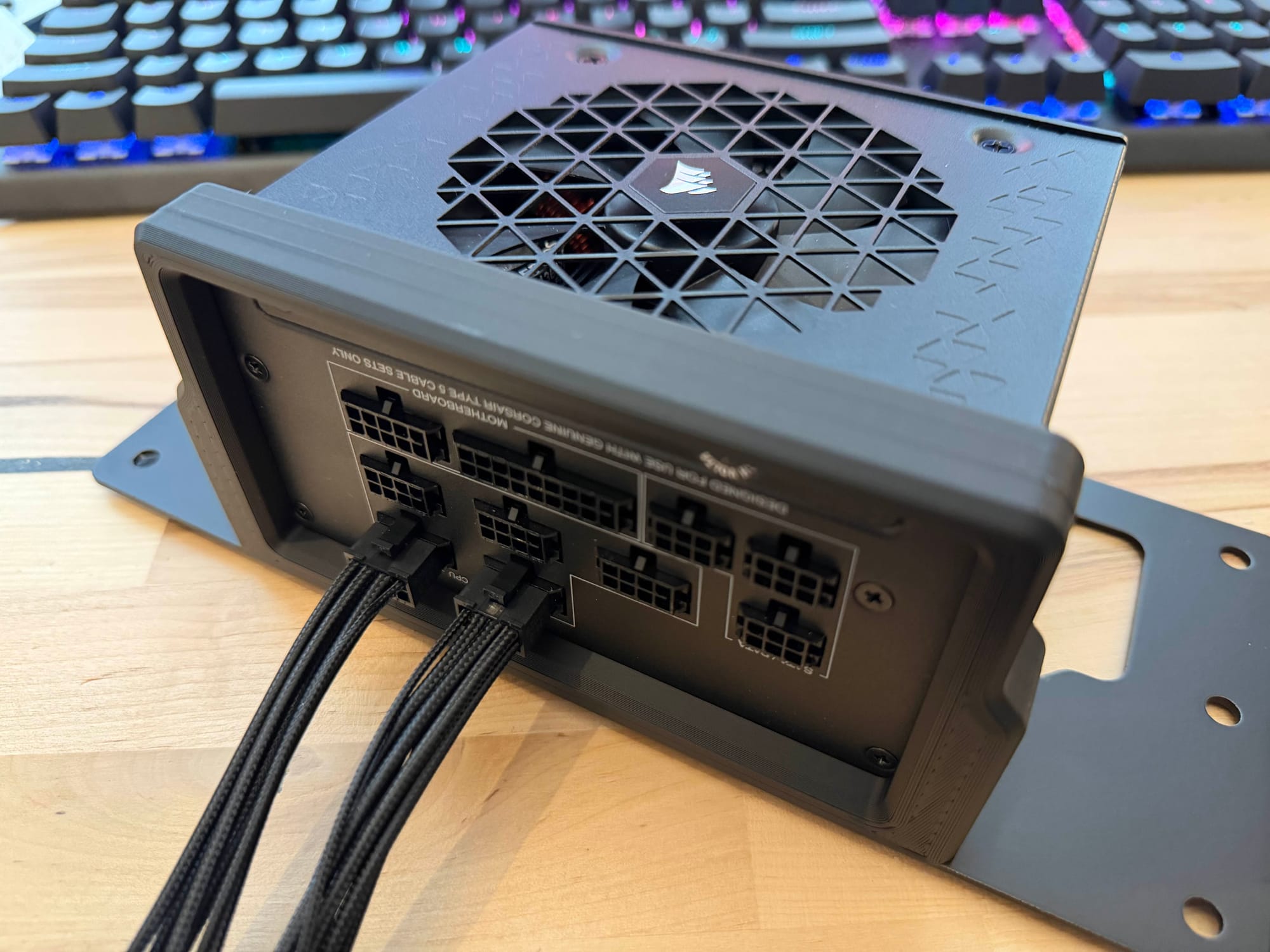
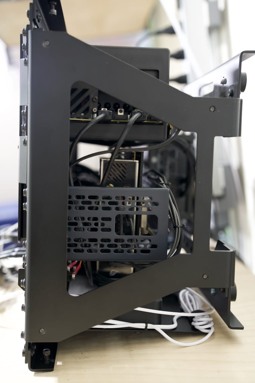
Rear Mounted SFX Power Supply
The rear mount that hosts the SFX power supply is comprised of a few parts- a metal bracket to mount it to the main frame, a 3D printed part to support the opposite end of the PSU, and a couple spacers to get just a few more millimeters of gap between the PSU and the DIN rail.
The photo below shows the metal end of the bracket, mounting with traditional PC screws.
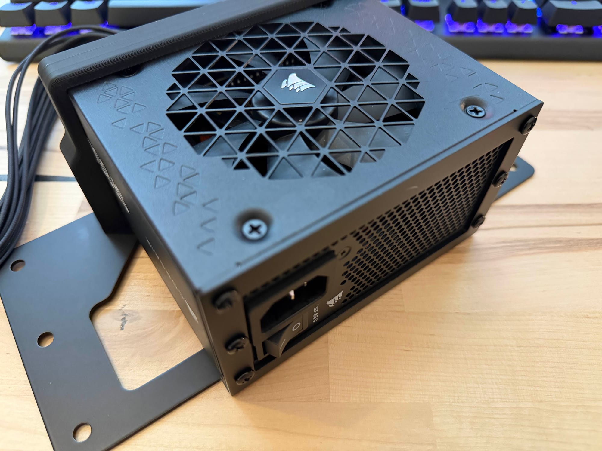
The opposite side shows the 3D printed bracket holding the PSU snugly in place.
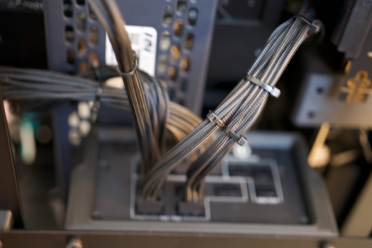
Who doesn't love zip ties?
Network Shelf
To really make this a Recovery Kit we need some networking- rather than just a simple network switch, we've added a full UniFi router and PoE network switch. While not shown in the build, this also powers a rugged outdoor PoE wireless access point. This gives us multiple high-throughput 2.5Gbps network ports for wired usage, and the network runs independent of the host system. The early prototype you can see below in grey, and even with other refinements it's still a little taller than 1U. This makes it a bit of a pain to remove, requiring the panel above to be loosened, but it's still fairly easy to remove and comes out as one full unit of router, switch, and PoE-capable power supply. Each networking component has its own dedicated C13 plug, so you can power each device independently.
This is where the Recovery Kit Ultra can really shine- this can be a PC for when the Internet goes offline, or just a LAN party- or both!
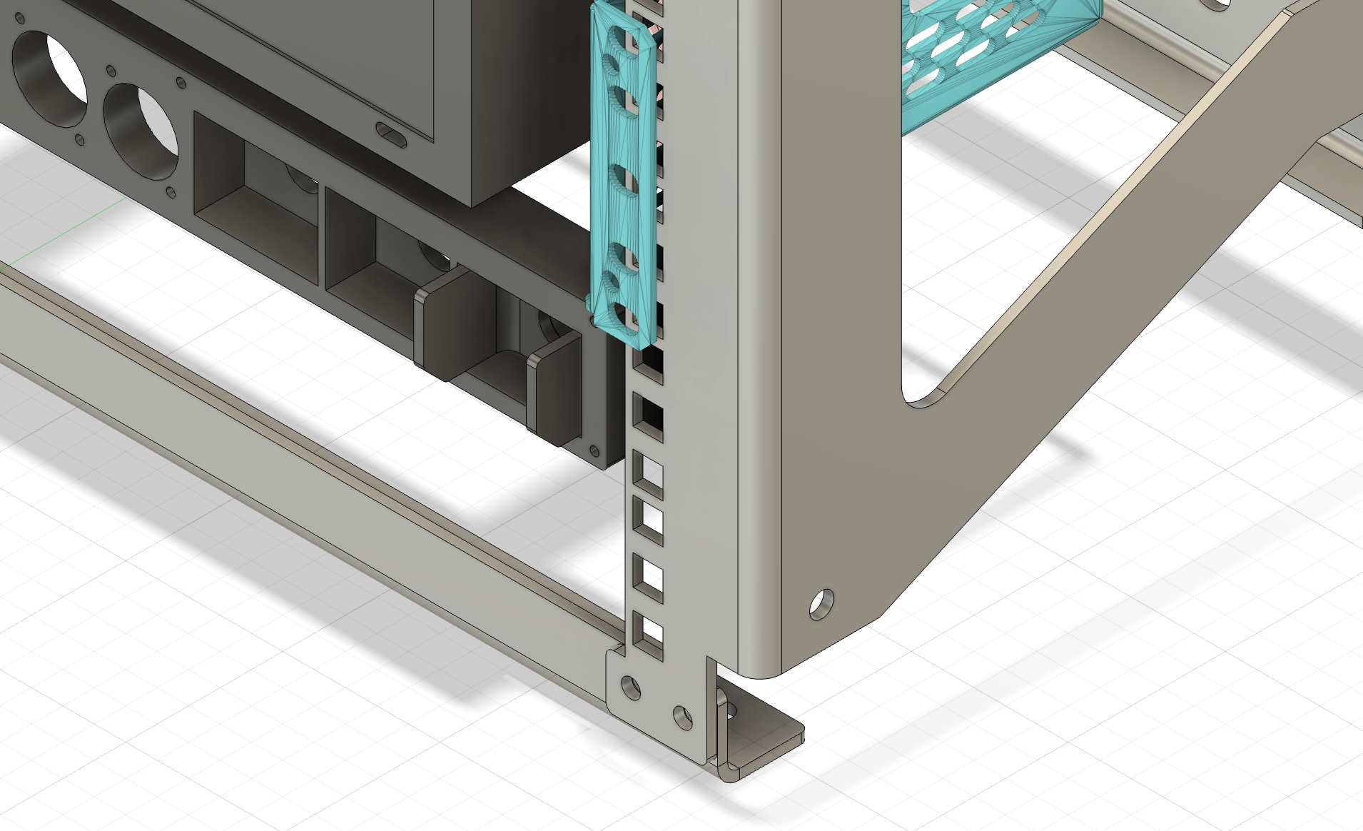
Shown below you can see an early prototype of the grey plastic adapter and grey powder coated shelf for the network. I'd normally rely on traditional mounts but these smaller consumer network items are meant for static mounting, and moving them around could cause the network components to disconnect if I relied on their factory mounts. The cage is meant to be minimal to allow as much clearance and airflow as possible- even with the optimizations the network shelf is a little more than 1U tall, something I plan to address in the future.
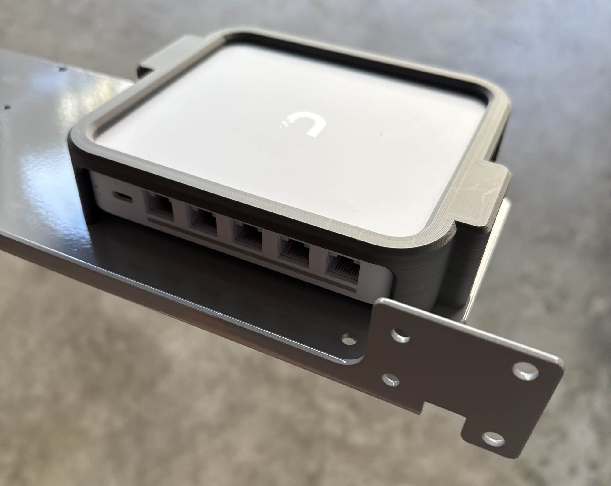
You can see the networking components slightly recessed below the main IO panel. They're still easy to get to for plugging and unplugging of network devices.

The patch cable between the router and the switch runs internal to the network module, helping keep it out of the way.
Motherboard & CPU Cooler
There may seem to be plenty of space in the photo below for a larger motherboard, but remember the GPU needs to go up top, and I am using a Corsair 360mm AIO water cooler for the CPU, and the radius on the bends for those hoses take up every last inch (or centimeter) of space to the left of the motherboard.
With the CPU cooler in place, the motherboard is no longer visible on the assembled unit.
The cooler is actually attached to the grill shown in the photo below:
No-Compromises PC - Hardware Spec List
In order to comfortably call this an Ultra, we needed more than a Raspberry Pi could offer here- so we went with a full-on gaming rig, admittedly just before the memory and storage prices rocketed out of control in late 2025.
- CPU: AMD Ryzen 9 9950X3d (16 Cores)
- Motherboard: ASUS X870-I ROG STRIX GAMING WIFI AMD AM5 Mini-ITX Motherboard
- RAM: Crucial Pro 64GB (2 x 32GB) DDR5-6000 PC5-48000 CL40 CP2K32G60C40U5B
- GPU: ASUS ROG 5080 OC
- OS/Primary Storage: Samsung 9100 Pro 4TB PCIe 5.0x4 m.2
- Secondary Storage: Samsung 9100 Pro 4TB PCIe 5.0x4 m.2
- Networking: UniFi Cloud Gateway Max and Flex 2.5 PoE switch
- Cooling: Corsair Nautilus 360mm AIO CPU Cooler
- Power Supply: Corsair SF850 SFX PSU
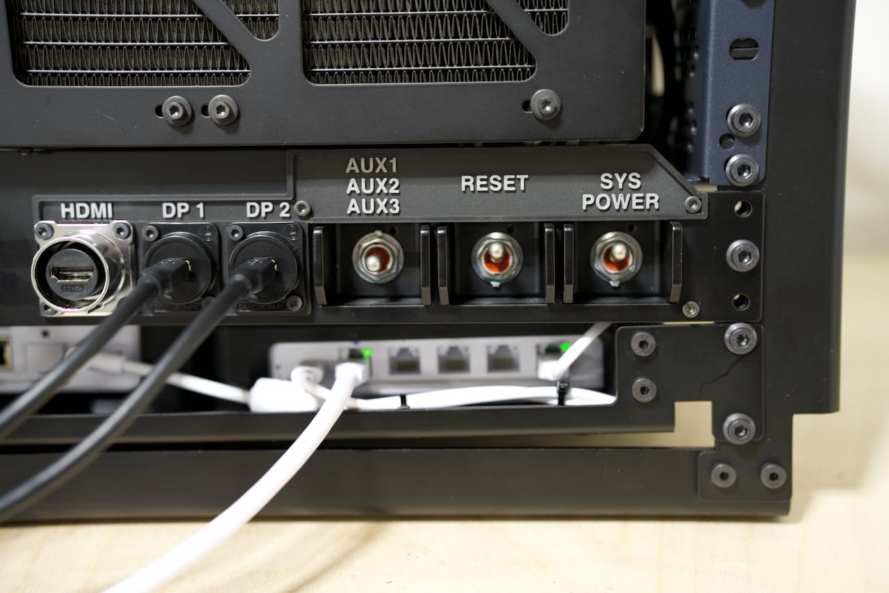
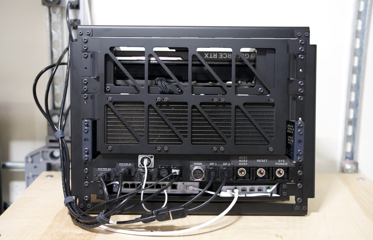
Panel IO & Wiring the Internals
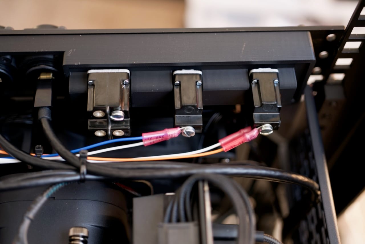
The panel inherits many of the same ideas from the original Recovery Kit, keeping that retro-futuristic and highly practical approach, just so long as you don't notice the price tag on sealed mil-spec toggle switches. In my defense, their CLACK is worth every penny. To keep wiring clutter to a minimum, I ran custom-length power cords for the internal power between the panel and the networking and PC power supplies. Each panel mount had a simple set on the back for connecting, including the 3x C14 power connectors on the panel, which are just connected via spade connectors to the power cords internally. You can see me doing fit/clearance tests with the spade connectors below.
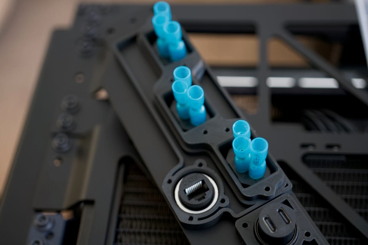
If you look closely you can see the rear of the RJ45 connector for the 2.5Gbe Ethernet. This may seem unnecessary but it's far easier to plug into the front panel of the Recovery Kit Ultra than it is to get into the rear of the motherboard each time you want to connect something. You can also see the USB-C connectors, which end up getting connected back to a mix of the motherboard's USB 3.x connectors on its IO panel. Those cables are extremely expensive to make custom, and I don't roll natural 20's on dexterity so I'm not making my own USB C cables. Instead, the cables are 3 footers and just run along an outside edge to make them fit just right in the build.
For the toggle switches, I had quite a bit of fun designing this bit. On the rear the multi-toggle switch is unpopulated for now, but the other two switches are connected via ring terminals to the reset and power pins on the motherboard. They really do have a loud, satisfying click to them.
On the front of the panel you can see the presentation of several materials, including the custom switch guard, which is power coated aluminum to keep the switch from getting hit sideways and broken. Here's the render of the guard by itself:
Now here's the guard with the plastic to keep it square:
The rear-mounted plastic parts do a couple things- first they help orient the front panel parts just right- like keeping the toggle switches and guards square, etc. They also replace all the nuts that each panel mount connector might need, making it easier to modify later, but also easier to customize for each part using a hole in the panel. For example, I could remove the toggle switches and replace them with any kind of switch without needing to redo the entire panel.
The end result is a rugged and symmetrical approach that is solved via the design process, risking less to mistakes during assembly.
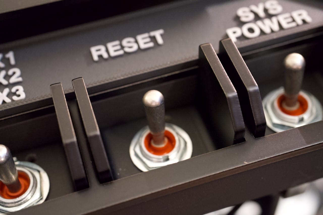
I may end up using a different approach in the future, but for now I am calling back to the original Recovery Kit with the panel labels- they are printed in dual color PLA on this build, with only 1mm of matte grey on matte black. The port label plastic part sits between some of the components and the metal front panel.
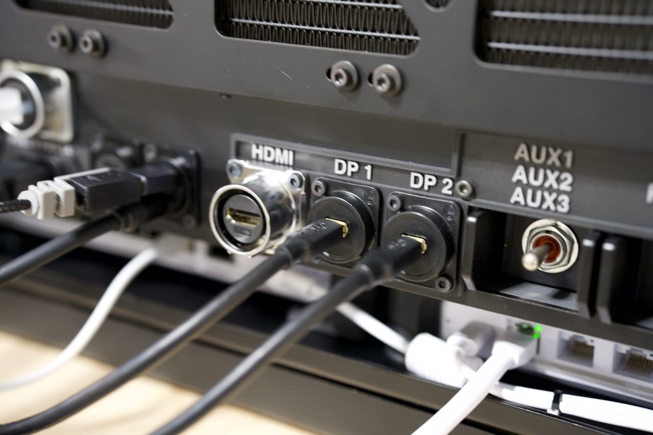
Display connections are modular, but I am relying on DisplayPort connections for two monitors currently, although the HDMI port works fine too. Just as on the graphics card itself, the display connections can change without needing to alter anything internally. I don't plan on doing dual HDMI, but if I did I'd need to drop one of the DisplayPort connectors.
I hope you've enjoyed reading through all the build details, and I am available for commissions on a limited. For serious parties this build is available for sale, contact me if you're interested.
For others interested in building one of these, the laser cut parts are available as a kit from the same shop I used- Send Cut Send, which I am using to host the parts build in their marketplace. I consider this to be a difficult build, so if you're interested in making one, consider the collaboration subscription on my site here to make sure you don't get stuck.
Thanks for reading, and the parts list is at the end of the article. For now, enjoy a few more photos!
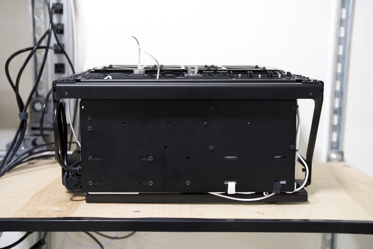
Below shows the bottom of the unit, looking at the bottom of the network shelf.
Opposite the network shelf is the GPU side with plenty of clearance for the GPU cooling fans.

Choose your Operating System
But wait, there's more! Although the system has Windows 11 on it, that's not for long. I am evaluating some other operating system choices to allow it to be multi-use as a gaming PC, LLM rig, and offline host for things like Wikipedia. There's plenty of space with two 4TB NVME drives, and in the future the GPU might be swappable for a disk array.
Subscriber Access
Thank you to all my subscribers- you have supported this build directly- thank you! There's a second post in your inbox and here on the site with the files for download. Free subscribers get the newsletter, paid supporters get access to all my STL and DXF files, and collaborator access gets access to the private Slack and other tools for collaborating on your builds.
I have a number of builds in the pipeline this year, with a new deck due out early summer and a variety of 3D printed and metal projects as well. Thank you for your support!
Parts List
- Design Files (Paid Access) - doscher.com
- Two Position Toggle Switch (Power and Reset) - McMaster Carr
- Three Position Toggle Switch (AUX switch, not yet used) - McMaster Carr
- Panel Mount C14 Sockets x3 - McMaster Carr
- Flanged M5x16mm Hex Socket Head Screws (for all front rack mount equipment) - McMaster Carr
- Torx Flat Head Screws (for panel mount IO) - McMaster Carr
- PCIe 5.0 Riser Cable - Amazon
- 2U DIN Rail - Amazon
- DIN Clamps x2 - Amazon
- Pelican Air 1607 - Amazon
- (External) - Mini DP to DisplayPort 1.4 Adapter x2 - Amazon
- (External) - USB C to USB Adapter (helpful for some mice and keyboards) - Amazon
- (Internal) - 2 ft. HDMI cable - Amazon
- (Internal) - Dupont wire leads for motherboard pins - Amazon
- (Internal) - 3 ft. USB C to USB cables - Amazon
- (Internal) - 3 ft. USB C cables - Amazon
- (Internal) - 3 ft. Ethernet cable - Amazon
- (Internal) - 4-pin fan extension cables - Amazon
- (Internal) - 1.5 ft. DisplayPort to Mini DP cable - Amazon
Comments ()